The Bad Side Sci-Fi Modeling.

Some people like to always keep things positive, or at least keep up the positive face no matter what happens. I grew up in a family like this, it was very difficult  as a child. Unless someone teaches you how to deal with problems, they never get resolved.

I see this sort of thing go on all the time. Sci-Fi modeling is no different, when people get what they want everything is great. They look past whatever is going on, as long as they get the model they want. If someone says something negative, he gets shouted down, he provides proof. He gets told to shut up, that is until it happens to them. Then they get to have all of that fun. The guy that pulled the con, shuts up and watches the show. Knowing it will never effect him. After all this business is a wild west of sorts.

That said…

Let me give you an example, like the wild west you sometimes have to take matters into your own hands. Here is my experience.

I keep going back and forth about this, to post or not to post?  Do I let it all go, and just take the loss and share the story with those were also wronged (when I come across them)? Or do I say something?  Writing about it will at least get it out of my system and warn others of such behavior so they don’t fall into the same trap. People should be aware of this kind of behavior, and hopefully be spared from what I went through. It has seriously effected my desire to do any modeling, whenever I look at this models. This situation is all I can see.

It all started with this little kit.

The 350 Botany Bay available from Fantastic Plastic, this is how it started. This is a printed model and mesh I created one evening for a model to go with my Custom Replicas 66″ E.  I scaled this one down and created it on my 3D printer. I posted it on a message board and a Garage Kitter I bought things from asked me to send him one. It was easy to make another so I sent him one. He thought the material was great he could shape it easily, he ask for a few changes so it would be easy to kit. I agreed and sent it to him.  I did get one of his kits, but one kit wouldn’t even touch my costs. So we struck a deal – I was to receive a much larger kit in return. To this day I have yet to see the larger kit, some 6 years later.  I saw on the boards that a few people received the larger model kit in question not long after I was promised one.  I even helped this garage kitter with printing and machining a number of parts for that model(1701-D).

From there the games began, he asked me create all sorts of stuff. One was a 1/350 scale K’Tinga. I was paid per kit for that one.  That’s what gave me the confidence to continue doing more work for the guy.

But whenever I asked for a kit, I kept getting excuses.  I even watched him give a kit away(it was a reject, but why didn’t I at least get a reject? Yea, good question). It took years, but I did finally get one. But not the original offering – I was disappointed, with this kit(the K’Tinga), no instructions. Sure the main parts are easy to place, but the little ones? I don’t know if I have them all.

In the meantime he kept asking me to make more stuff with the promise of money from the sales of the models he was to make with the parts I sent him.  You guys would have had some really neat kits if things worked out, years before anybody else. I could list them but what’s the point.

He asked me to help with a studio scale Star Wars subject(Slave 1) – he asked me to scan a known kit.

I did and redrafted the mesh (that took about 30 hours) then printed out the huge pattern.

I was paid for additional printing materials (binder and powder – at $500/gal.  $1500 per container of powder for the 3-D printer of that day, no it wasn’t cheap).  The money given wasn’t even a third of what the pattern cost me to make. I still haven’t seen anything of this model – last I heard people were still arguing over it. It has a novelty factor, but not something I would have done on my own.

But he has one.

Then came the big project, not the studio scale Enterprise, but the Defiant.

This one involved all sorts of work, breaking apart a mesh, redrafting parts, printing parts, routing parts, scanning, routing and printing more parts. This one was getting real costly in the end it was over $15k worth of work.  The mesh he told me to use wasn’t the right shape, so he will have to rework the parts I sent him. So I did all that work for nothing(At least that’s what I was told), on a model I have no interest in, and never would have made in the first place. (The kit came and went, I never a dime or the kit. Deal busted!!!)

At this point I began to realize that many things I had been told were not adding up. But they were adding up to the fact that I was being lied to continuously for several years.  I was told:

“I’ll send you one.”

“I kept asking you make more things in hopes one of them would make money.”(Trying the same thing over and over hoping for a different result is insanity, a red flag, and makes little sense).

“I didn’t want to tell you the printed stuff didn’t work, because I was afraid I would hurt your feelings.” (I didn’t know this was that type of relationship, that’s normally said when someone doesn’t want to deal with a situation.) Whether or not that was true, that was the wrong thing to say. I have different types of equipment to do different things, a 3d printer can make all sorts of parts. But it can’t make up for other pieces of equipment. I have no attachment to any particular process, only getting the work done right. It’s like saying my heart is in my pliers, so I will be offended if I have to use a socket wrench. Things would be very different today, if some honesty was employed.

On top of all of this I was promised one of every kit offering he made.

Didn’t happen, I only got stuff he couldn’t sell. It was all little stuff, and what I really wasn’t all that interested in.

Which means there was no intention to pay me back for the work I did for him. The hardest part of it is that I thought I had a friend.  I did everything he asked (I would do that for friends, not any more), instead it was part of a game.  All to get a bunch of stuff from me for free or very little.  I even sent him back a kit I bought from him(he was apparently in a jam) at his request.  I had already spent weeks fitting the kit. It took me a couple years to get a replacement kit from him, he never tried to offer me a refund.  I asked him to fit the new kit, since mine was already fitted. Nope, I had to do all that work all over again, and on top of that he didn’t say thank you for getting him out of a jam. Instead he complained that he had to buy me a replacement kit(If he didn’t want to look a jerk, he could have at least acted like I helped him out).  So I can only conclude that he was thinking only of taking advantage of me.   This behavior was clearly not that of a friend. At least I saved all of the e-mails.

But being told “I had to redo all the stuff you sent me,” was the last straw.  If he so much as put a ruler next to a part, he used it. Did he expect me to say, “that’s alright I’ll eat all of that, and be happy with nothing.” That isn’t the way the real world works. If it was, I would be a rich man getting all of my money back for the things that I paid for in the past that didn’t work. In the real world you have to pay, even for mistakes. And they charge penalties and interest so do I. I do have books to worry about.

The last thing I did for him was some drafting(24 hours worth) in 2011 it was for something I never expect to see(1701-D), the last model I did for him was Defiant in 2008. I’ve only received a few things here and there. But nowhere near being equal to the amount of work I did.  I’m still way in the red here, after this much time I’m considering myself screwed over. But I’m still calculating interest and late fees.

The most recent discussion with this guy was an offer to do work for some company he is now working for.  I about laughed outloud, “How stupid does he think I am?”  I don’t care who owns the company. Out of my past experience with the guy. Why would I ever trust him or anything he is involved in. After all just about everything I sent him, I never saw again. All the work I did was for nothing. That bridge was blown up and burned, only this wasn’t Thunderbirds.

Why post this?

Simple enough, I have nothing to lose.  I look at my models and all I can think about is this situation. I’m pretty much out of all of the loops(if I was ever in the loop?). I only look at the boards on occasion, to remind myself why I don’t want to go back. I’m not after any reference, nor am I selling any kits. If I do offer a kit, people will buy them, they really could care less about any back story.  As long as they get what they want.

All of this experience has really put me off of modeling. Even worse, I find myself not trusting anyone these days. It’s frustrating because I really like helping people, offering advice, solving problems and making things.  It is true that one bad apple can ruin your day or your hobby.

The good side of this is that a bunch of people got some real neat models.  I got squat.

All of this is posted for the benefit of others, perhaps someone will spot the same signs. And get out before they lose their shirt (or worse).

If you find yourself wanting to partner with someone here is some advice, mainly to protect yourself from what happened to me.

1. Get any agreement for trade or payment in writing signed by both parties.  Make sure the agreement does not leave you hanging – get a deposit of some sort before you start.

2. Document everything, take lots of pictures. Even of the packages you send.

3. Keep all documentation, create folders for each project, print out e-mails, save receipts.

4, Meet them face to face. This will not protect you but at least you can put a name to a face.  A disembodied voice on the phone is easier to take advantage of.

5, If they state another party will take care of the trade contact that party immediately. Verify that they are going to take on the obligation. If they have no idea about it, someone is lying or both are lying, You have no way to tell. If everything is ok, still get it writing with all parties involved.

6, Take notes, if they state, “I’ll send you one” send a follow up Email or letter putting this in writing and ask them to sign it, at least you’ll have a record, but that isn’t a guarantee of anything.  Note the date of when they said it. Hold them to it, if you never see said item. Hold up any other work until you receive said item, or drop it and quit.

7, Look for changing stories, if suddenly your deal is different than the one you agreed to. Ask why are things different, when you didn’t agree to it, and reference what you have in writing. At that point things have gone wrong, your in trouble.

8, If another party is involved at a later date, the original deal still stands unless everyone agrees to a new deal in writing. When they bring in another party it only means they owe one more person. Saying the deal has changed is an excuse to get out of something, again if this happens things have gone wrong.

9, Never be the guy behind the scenes.  I understand why people want to do it. But when things go south you’re out of luck with any proof. The more public you are the better.

10, Reference isn’t a valid trade, if someone says, “I’ll trade you reference,” don’t do it. It’s no good if you’re not interested in the subject. Even if you are interested in the subject, who knows where they got it – illegally?  Bad reference? It’s a very one sided trade, and you’re on the wrong side.

11, Celebrity and/or reputation are irrelevant, I’ve been ripped off and promised stuff by people who are well known in the hobby and industry with great reputations. They are still human just like all the rest of us, some think they can get away with more because of their status.

12, Apologizing publicly/privately shouldn’t be accepted.  If they are truly sorry, they will do something about it. Using words is cheap and easy, deeds are not as easy. Even if they send you a formal written apology, that’s no different than telling you what you want to hear, is just as easy as talking.  After all how can you take the word of someone who said, “I’ll send you one”, and never does. That is what is called lying, why would an apology be any different? Those are only words no matter what they say, it cannot make up for the time/money lost.

13, If all else fails, regardless of excuses call them out publicly, be a pain in the rear. (Do not do it with a bunch of typing, provide proof, pictures, e-mail, links etc. Nobody will take anyone seriously with a bunch of accusations, but proof of the work is harder to dispute). If they are ripping you off, they are going to rip someone else off. Nothing makes people special, defending the con man, attacking the accuser, having money, a return customer, it doesn’t matter. Screwy is screwy. It’s only a matter of time before it happens again to someone else. If you are a pain and someone says they will not sell you anything that is their prerogative. But there isn’t a Garage Kitter out there who would refuse money, since they do not have much of it. But if you’re a known pain, you should get better service.

If someone tells you “don’t say anything about our deal,” or “don’t talk about your bad dealings with that guy,” those are red flags.  It’s like not telling the police about a guy who is robbing convenience stores.  Hoping he will stop doing it at some point. There are circumstances where you do not talk, I normally don’t. Until I’ve had enough.

I’ve had enough.

-Update 10-5-13-

I keep finding work I did for this guy. Man was I an idiot.

rsd2 rsd

This is a Republic Star Destroyer, who knows what became of it. Here is a little peek into my process.

rsd4 rsd3

These are layouts used to create toolpaths for what I call cookie cutter parts. Toolpaths are where I want my machine to cut. But it isn’t as simple as layout the parts and go. I have to hold the material in place while I cut it. So I first drill holes for screws to hold down the material. After the holes are drilled I place screws in each one. That gets real tedious it can take hours, depending on the material. In this case it was plexiglass, I’m sure I didn’t get reimbursed for the material either.

For those who want to know who this guy is, his name is Richard Long he owns Sovereign Replicas. He goes by REL on the message boards. He is married to Dana Long and I last heard he is working for a company called Titan Models.

After this post was up for a while I heard from him. What did he say?

Promised me more stuff, that he will never deliver. While saying how sorry he is, words are cheap my friend. Actions are not. Forgiveness only comes when ALL deals are completed to my satisfaction, after all I did everything you asked. What did I get in return?

My advice would be to avoid direct dealing/trading with the Longs. He does deliver if you pay him(at least that’s my experience).

I can only wish the company he works for luck. I haven’t had any dealings with Titan Models. Because of REL’s behavior most likely I never will. That includes anything I might sell.

-So there’s more 11/4/13-

Yes there is.

I’ve heard from a number of people who have had the same thing happen to them.

Guys creating models either by drawing or physical models. Told they couldn’t use it so you get nothing (if only the real world worked like that). People would be surprised who pull this game. I sure was, but I can’t go into it. After all it wasn’t my experience, I only have one guy screwing me over.

Speaking of things they couldn’t use.

slave_body_16 slave_bdy_01

These are the printed parts for the Slave 1. I was told the parts I printed were useless. I have to call BS, here they are. Of course some other excuse will be made up. This is the game, since many others are told the same thing. It’s just doing business in the Garage Kit world. One of the things that can protect you from this is the points I made above. (I have all of my e-mails saved for about the last 10 years). These images are from 07 & 08 along with all sorts of info about all projects done for Richard Long. It’s too bad I can’t post the e-mails. We were having a real good time, which is the hardest part of this. But then I come across the excuse e-mails.

But there’s still more.1bb

350 Botney Bay being being de-powdered. It was used as the master for the first run of the kit offered by Richard Long(REL).

21kre

1000 scale Reliant years before anyone else. I have no idea what happened to this, it was mailed to Richard 8/17/07. I did find a few mentions of it, but after a while it faded away. I’m sure I’ll get some e-mail about it. For all I know it made it to a kit. But how I can I believe someone who never kept his promises.

31kkting2 31kkting

These were the start of a 1000 scale K’Tinga. Again it’s fate is unknown. I know, I can’t use it, bla , bla.

5relparts

More Reliant parts, in the days before the 1000 Refit. But look at the top.

4350rel

350 scale Reliant, designed to fit the PL Refit saucer. I never shipped it out, but it was a requested model. There is correspondence about it. It was destroyed years later by one of my cats. I was glad to see it go(I can’t stand the Reliant).

5drfb1 6defb2 7defeng 5defnose

More Defiant parts, and parts in use.

problem

This is it for this one, (I still have more stuff I could post). I will write more on the Garage Kit subject in the future. But as far as dealing with the Longs go, I’m sure Richard will not come through on anything he promised. He has no intention of it, his track record proves it. The only model he came through on was the 350 K’Tinga, even that took years to conclude. After all that was the hook, I thought I had a friend and he took full advantage of that.

As far as money is concerned he owes me in the five figure range(I charge interest and late fees, the longer you take the more it goes up) . If he sent all that he promised, I would have never made this post. Most likely we would have been turning out stuff galore.

But this is how guys like me are treated in this hobby. Used and discarded, where the real losers are the guys doing the using. They throw out the talent for the sake of a few pennies, thinking they are making money. While the hobby suffers a little at a time.

While driving the talent away, that make things like the Studio Scale Enterprise.

If you were in this business, would drive away people like that(me*)?

*One other thing, I was a paying customer I spent a few thousand on Richard Long’s(REL) kits. I would have spent a lot more if I wasn’t promised free kits in exchange for work.

-Small update 1/29/14-

Many thanks to my friend and Stinker in Fellowship Steve Neil. Because of him I’ve heard from even more people. I didn’t know Mr Long put his Enterprise D’s into production. I was talking to him with regularity all he said was how things were not working out with that kit. Just goes to show how a con man works.

Keep in mind when you See Dana Long on Facebook, she is fronting her husband’s Ricard’s work. He did want to get out of the public eye, now you know why. Of course don’t forget Titan Models he is hiding behind that as well.

7/15/14

After cleaning up my garage a few more items surfaced. Here is more of my process.

dgus

dgus1

What’s left from cutting out armatures for the Sovereign Replicas, 650 scale Enterprise D. The top image is what I used to create the toolpaths for the machine. The image below that is what was left over after the parts are cut out. The series of holes around the parts are used to hold the material in place. The parts in use shown below. There are more parts to this armature than I have shown.

d_armature_777

There are at least 6 sets cut out of plexiglass, 2 out of aluminum. That’s parts for 8 armatures, which is in line with the numbers of castings I’ve heard(and seen pics of) he made. There is one other thing, once he has the parts I cut out, he can use them for templates to make more. So who knows how many of these were really made?

I made a set out of aluminum as well, I saved these pieces I thought they were cool.

edscrap

edscrap2

Is that all I did for the SR D. Nope, I did some printing as well.

dnac

Which of course he used/couldn’t use. I didn’t create the base for this nacelle. I have no idea where he got it. But it was printed and shipped. Sorry I don’t have the pics of the printed part.

And…

These some would find interesting, it’s the last thing I did for Long.

aztecs top

aztecs bottom

They are the tracings of the decals from a model kit. It wasn’t any fun to do the work, I couldn’t find any logic to them. They are so stupid, I can only assume they were designed with the help of hallucinogenic drugs.  I’m posting the images to prove I did the work, Long never delivered a casting a to me(as per the agreement). So I never sent him these files.

I have no use for these files, to me they were an exercise in futility.

Here is another part knocking around my garage.

s1buck

It’s a vac-u-form buck for the Studio Scale Slave One clear canopy.

I’ve seen some guys talking about this subject, my recollection of the project is very clear. I left out info and others involved. Since most of my info was coming from Long. Who knows what he was telling me was the truth, nor do I have any idea of what he was telling the other parties.

Is there more, yes. Is there another side to the story, I’m sure there is. Whenever I asked about sending me something he owed me. All I got was an excuse. The other side of this is obvious, take as much as you can from everybody you can. Then delay, obfuscate and repeat.

Richard Long really missed his calling as a low level bureaucrat, attorney or politician.

The garage kit world can be fun, but you have to be very careful. Long isn’t the only crook out there. There are a number of individuals that use these same methods. Research the people you want to do business with, ask around there are many old timers who will be glad to tell you about their experiences, good or bad. Most of all don’t get distracted by something you really want. Think before you pay, you might not ever see that money again.

This is it for this post, unless I receive what Long owes me. Money and models, I will post that info. I’m not holding my breath.


Models and Props, Off Topic

Round 2 1/350 Enterprise or Why Did They Do That?

I don’t know what it is about this model, but people love to make this subject more complicated than it needs to be. This kit has a number of things that made me wonder, “Why did they do that?”.

The original Enterprise is a fairly simple design(some would argue this), at least in comparison to the later starships. Those of you familiar with this site know I have some knowledge of this ship. Nor do I pull any punches.

First off, once you take the kit out of the box. You’ll never get it back in. This thing is packed tight.

Man, it’s a small model. The only E I have been looking at lately is 66″ long. Yes, this is a small model. As I call it the “Tiny E”.  Here are some comparisons to the 66″ model.

Talk about putting things in perspective, this image makes it obvious.

The saucer, all I can say is what a headache. R2 was going to put it on, no matter what. I guess they believe people can’t use a pencil, or model builders can’t align decals. This is a small model, you align decals from your landmarks, and this model has loads of them. No grid was necessary, it will only act to intimidate the novice modeler. R2 really doesn’t care about this, they got the sale. Who cares if the model ever gets built. Sadly the majority of models sold will never be built, or worse the modeler will get frustrated and put an unfinished kit back in the box.

A friend took one look and said, “That would be so much work to fix, I would leave it alone”. And we thought the MR E had issues with it’s grid.

Note the center ring, what I want to know, why wasn’t that a separate piece? It makes filling in the grid all that harder.

The other glaring problem is the spinners, these have to be replaced. This is bad.

Note: the spinner has straight blades. This this is wrong, me and countless others have tried this same trick. It doesn’t look right, the originals were tapered(even the MR E was tapered). The other problem the blades are inset, which means they will show up with the lights behind them. Then there is the center shaft(The spinner shafts are different sizes so one fits on the motor shaft, the other doesn’t), that was a real problem on the MR E.  But then I thought the spinners on the MR looked awful. Hopefully this one can be much better. First you have to replace the supplied spinner. I’ve got a fix, I’m saving that for a later post.

These stuck me as odd, the bulbs used in the 11 footer were all c7 Christmas bulbs. I must assume they were trying something to be different. I’m not using them in my model. They didn’t fit my modifications.

Here is one that was under the, “Why did they do this?”. This looks familiar-

Looks like-

I did this for scratch building reasons, it hits a PITA(Pain In The Ass) factor in a styrene kit. The parts do not fit all that well(easy fix), so it’s under the “why” category. If I was the inspiration for this I’m really sorry.

Here is a comparison of the accelerators from all three models.

I showed it to a friend of mine(who is one hell of a modeler himself), he was laughing trying to fit the accelerator parts. Lets just say they need a little work. It would have made more sense to make the part one piece.

The more I dig the more I find. Here is a problem common in the garage kit world.

Seams through detail, I’m sure there is a reason(thank goodness the part is small). It’s another little thing easily rectified.  Most of the time I’ve seen this in Star Wars garage kits. For the modeler it could be another headache. It depends how far you want to go. I wouldn’t have bothered mentioning this, if the pilot version had the same thing. But it doesn’t. I assume they were concerned about the detail hanging up in the molds.

I really like how the window strip works, again no big deal, but it looks like things were done in a hurry.

There are too many windows with this kit,  three sets came with the kit, clear, white and black. I used some of them for masking areas I didn’t want to get paint in. Overall most of the windows didn’t fit all that well. My suggestion is to use Steve Neil’s dental acrylic trick. It’s real easy to do, and since not all of the supplied windows fit all that well. It will have much better results in the end.

The shuttle bay, oh man these guys are inconsistent.  Ok the Refit had a shuttle bay that can be made separately from the model. Not this one, it has to be in there. I think this was a really dumb idea. I mean really dumb, even worse the shuttle bay status windows are not clear, nor is the window above the doors. What if the builder wants to light them?

Perhaps this is rectified in the light kit. I don’t know. I’m not bothering with the light kit. But I’m going to light it anyway. That’s something I found annoying all the extra stuff you have to get to make your model that much better. Why not put that effort into the original model? Then leave the extras to the Garage Kitters to offer. The model and extras will run over $400.00(if you get them all), at one time you could have gotten an MR E in the $500 range(free shipping) then you didn’t have to build a thing.

OK, so I’m putting out all of this criticism. So to put my money where my mouth is. Yes I’m building this kit. I do have some experience fixing model kits. Plus I have a much easier way to get rid of the grid.

See no grid, Steve will be very happy. Smooth E’s are the best E’s.

The verdict, it’s a build-able kit. The grid is it’s biggest issue. If you want anything resembling an accurate model it has to go. The spinners are the next issue, along with the shuttle bay. The model is straight in a dry fitting(I wasn’t expecting that). I wouldn’t recommend it for a novice, but then it’s not priced at a novice level.

For R2 to keep to form they have to screw something up. I haven’t seen a kit of theirs that didn’t have some issue. It’s too bad these guys do not consider garage kit maker’s techniques in designing kits. They would save a lot of money in producing these models. Like not having to make the molds for so many windows?


Models and Props, PL Tiny E

Big E Posts From The Messageboards

I realized I didn’t have some of this information on this site. Since I’m no longer posting on message boards, I figure the information would be better off here.

Here are my posts from the RPF(replica prop forum).

Posted 1/12/11

This is the big one. Not many models come bigger.

I’ve been working on this project for a while.
I thought you guys would like to see my progress.

I’m building the Pilot and Production versions. I’m thinking about making them available as finished models. Kits wouldn’t be very realistic.

These bridges were printed, and still need finishing.
But you guys might want to see more. OK, here is some more.

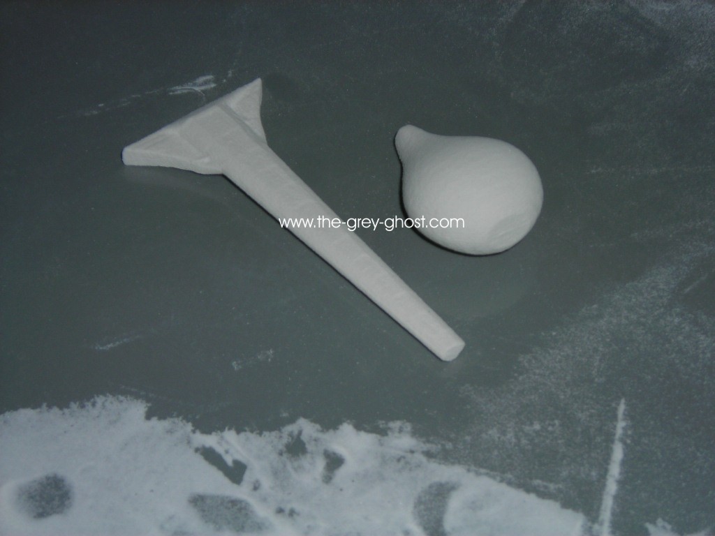
Deflector dishes in a row, SS, 66″, 350 scale and 18″. I printed the SS dish for reference, the final will be metal.

Some of these parts should look familiar. Even the elusive pink Christmas bulb(well not that elusive).
What I was very happy to find was the original gearmotor.

I can say the warp nacelles are very big.

Very very big, the rectangular blocks are 1″-2″-3″.
You want to know how I did them.

They are particle board, milled to a base shape.
Covered with Bondo and milled again.

These are nearly finished, I just have to mill off the ends. The printed parts are placed for fit.
Want some more…

Here is the neck, about half done.

This is what the part looks like after a few hours of running.

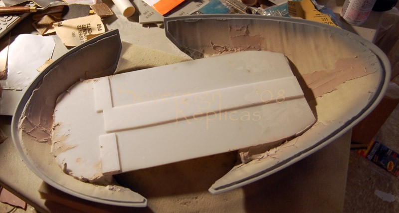
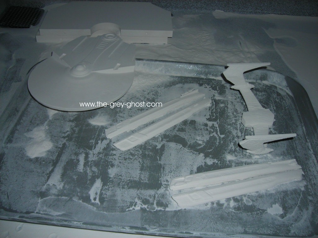
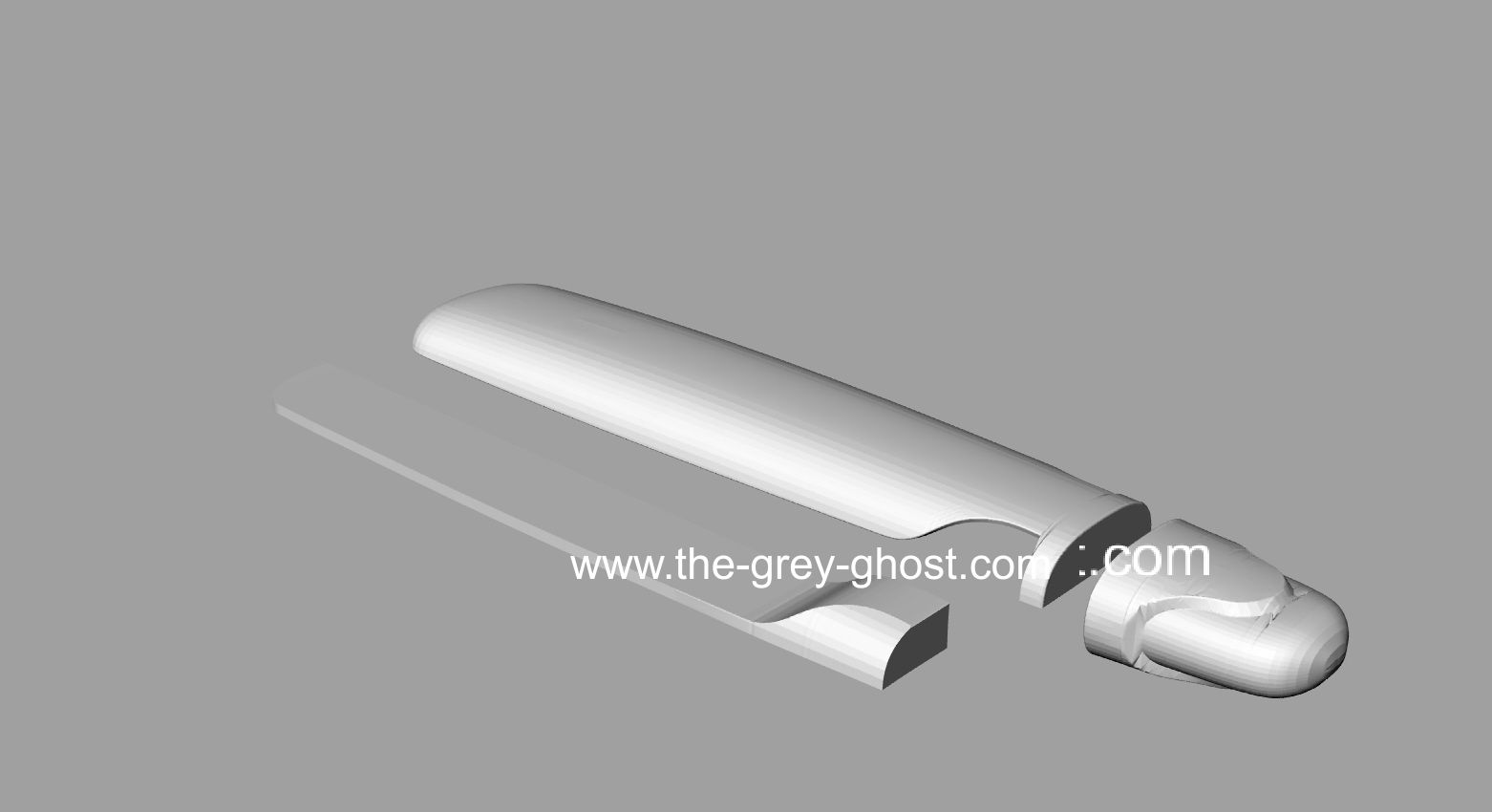
Here is one half of the secondary hull.

It’s big, note the milled surface. It cleans up very quick.


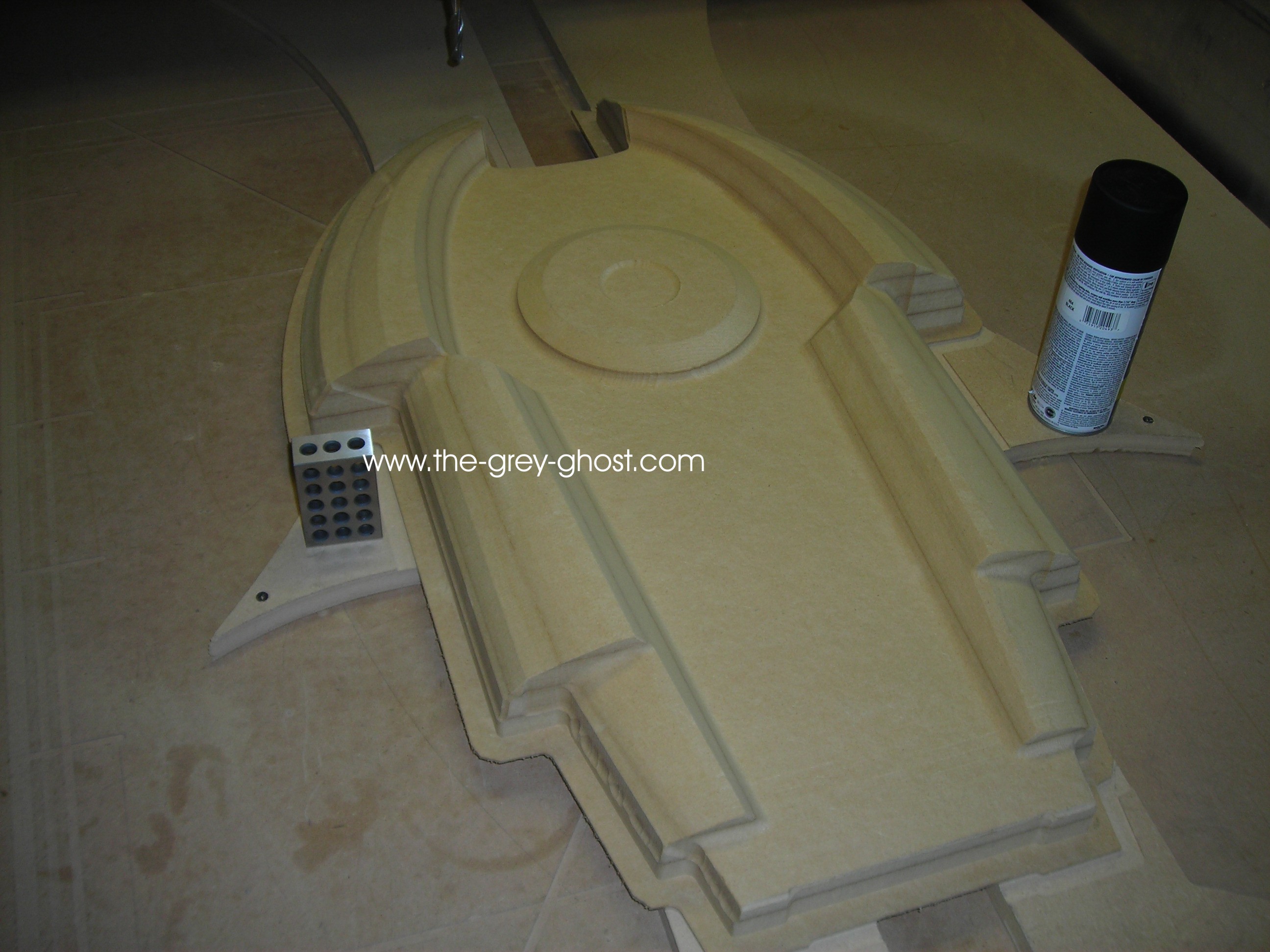
This is what people want to see. This is the upper saucer, it’s done as a 1/4 negative mold to save time and space, the saucer would be about 5 feet in diameter, using traditional methods the molds would be monsters. The ship will be cast in fiberglass.

The sensor bands proved to be problematic. They look great in the pic, but cleaning up the tooling marks were not going so well.
So I’m using an alternate method to save some time and headaches.

I milled groves for the bands, so I can place a 3/8″ round and fill in around it. After I’ve sanded the part smooth.

That’s all for today.

Posted 1/13/11

Thanks guys,

CD I’ve never seen that, thanks.
Funny thing I’ve never seen the original ship in person either.

I did have earlier go at the saucer. I did these in 20O8.


This is what made me realize I needed to do something different for the saucer. And I needed to make more room to construct such a model.

Trekman1017 I’m making the second pilot for myself. I designed both pilots so I could make either one.

Clay, sure I will make you one. I don’t feel comfortable giving any particulars at this time. My goal is this year.
I started machining the parts in October.

Posted 1/13/11

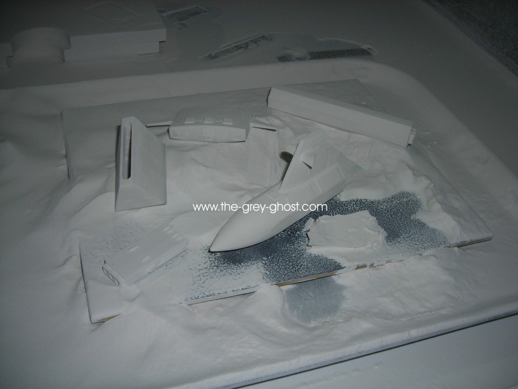
Here is some more for you guys.

This is how you can make Bondo cake.

Start with a filling of MDF…

Cover with Bondo…

Mill to shape.

Add what I call the “Nubs”, I machined those separately. I’ll show those in another post. I was surprised the fit was so good.

This is the part removed, with some of the nubs set on the deflector ring. I revised the nubs when I realized I would have a heck of a time putting the parts together.


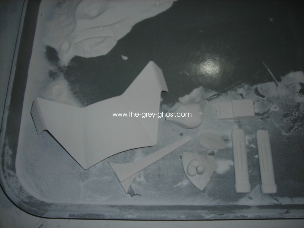
Here is the impulse drive. I had to split it so I could print it. It still needs to be finished as well. Note the change in shape on the right side of the part(just above the ” 24″x36″ “) that’s what I consider to be a tell for an accurate model of the E. Because it’s real easy to miss.


Here is the accelerator and the lower dome(from the primary hull, weapons array?). These were printed as well, I left out the strip in the accelerator. It’s easier to make a piece of styrene to fit than to make a flat printed part flat. The printer works best with organic shapes, but it leaves a very grainy surface which has to be filled and sanded smooth.

CD to answer your questions, I wasn’t planning to put a shuttle bay in the models. Really I never thought of it, I would need to know how far back it goes into the 2nd hull. A shuttle would be 2.75″ long, the Botany Bay @ 4′ long, D-7 @ 8.89′ and BOP @ 5.11′.

To answer the question of display, I was going to mount them high enough to be able to walk under the saucer(I’m 6’3″ so that will tell how high it going to go) and incorporate a circular display cabinet below the models. With the whole thing on industrial casters.

My background is in designing a variety of stuff, from artistic items to machines. Finding the same type of gearmotors used in the spinners(at the front of each nacelles). Was a matter of looking around the surplus sites, and E-bay. This picture was a real help.

It gave a shape and a dimension. Take a measurement across the front of the nacelle, and look for a part with similar specs. Electrically the E is very simple, these motors run on 110 and use a pot to control the speed. I still have to layout the motor mount and how I’m going to place the lights(I know where they go). I’m using the original Christmas lights. I don’t like the look of LEDs on the other E’s I’ve seen. Any ships I sell will have LEDs, I’m only using the the old style of lighting on mine.

Thanks for the offer AD, I had the same idea about a month ago. Using automotive vinyl is far superior to decals and saves a great deal of time on painting. I’ve already created most of the masks, having a 3d model of the subject makes that process a lot easier.

Thanks all for your support.

Posted 1/14/11

More updates guys.


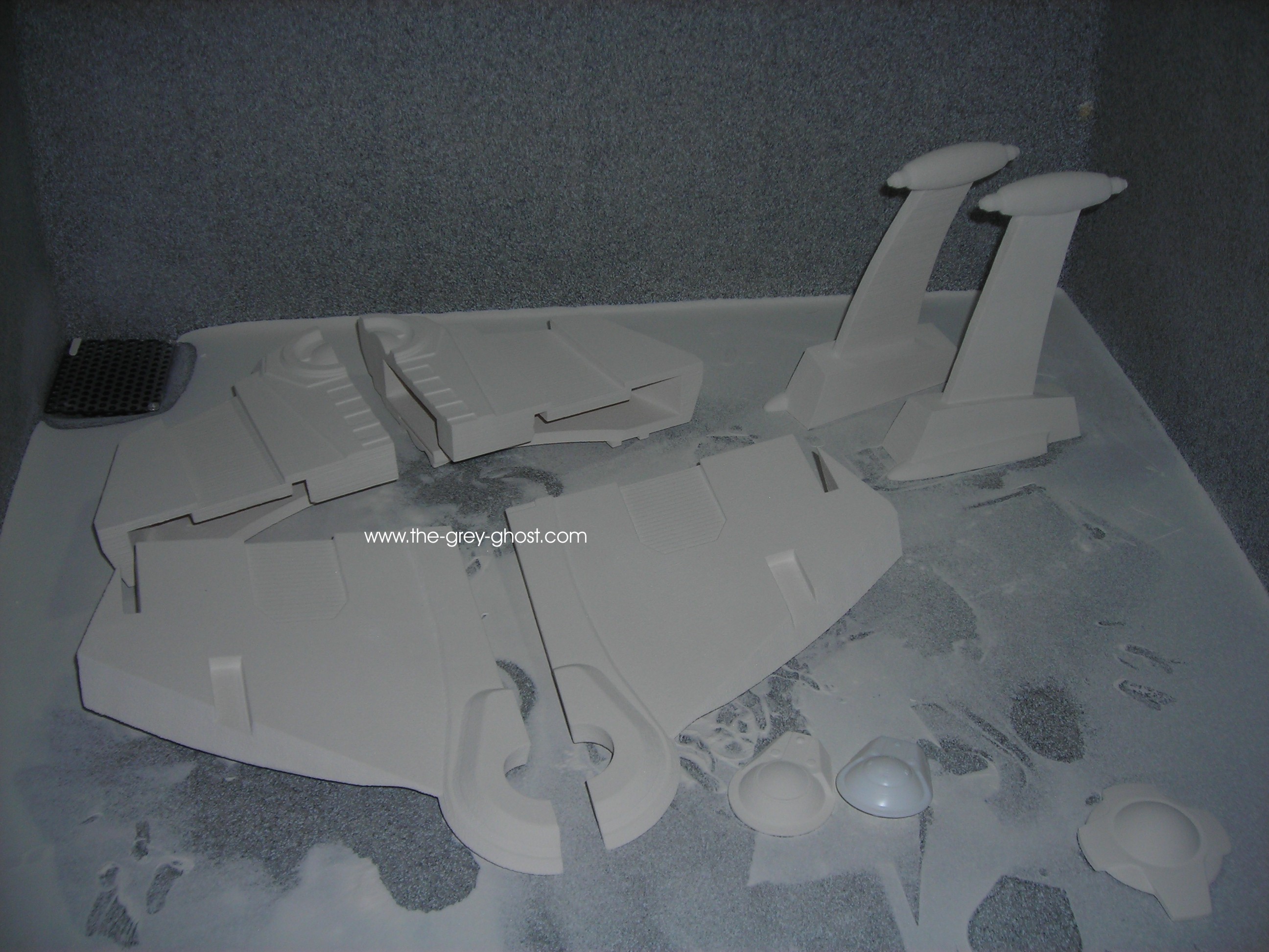
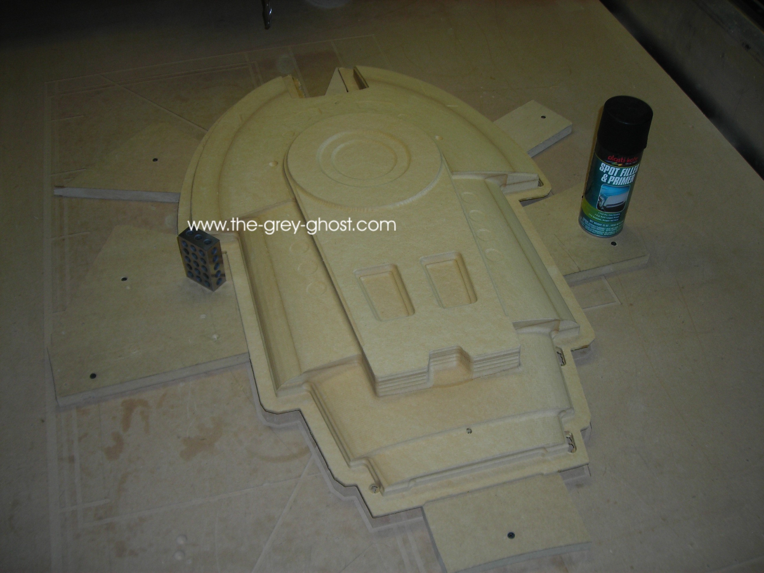
Here is the parts for the shuttle bay. The parts are just set in place, to see how well it’s going. I cut off the secondary hull in this manner to simplify assembly.

This is where this technology really shines. I printed the fantail long before I machined the hull, I can’t place the shuttle doors since they are partly inside the 2nd hull.

I used my old nubs to show how this goes together.

Now for the engines, since they are symmetrical I only need to make one.

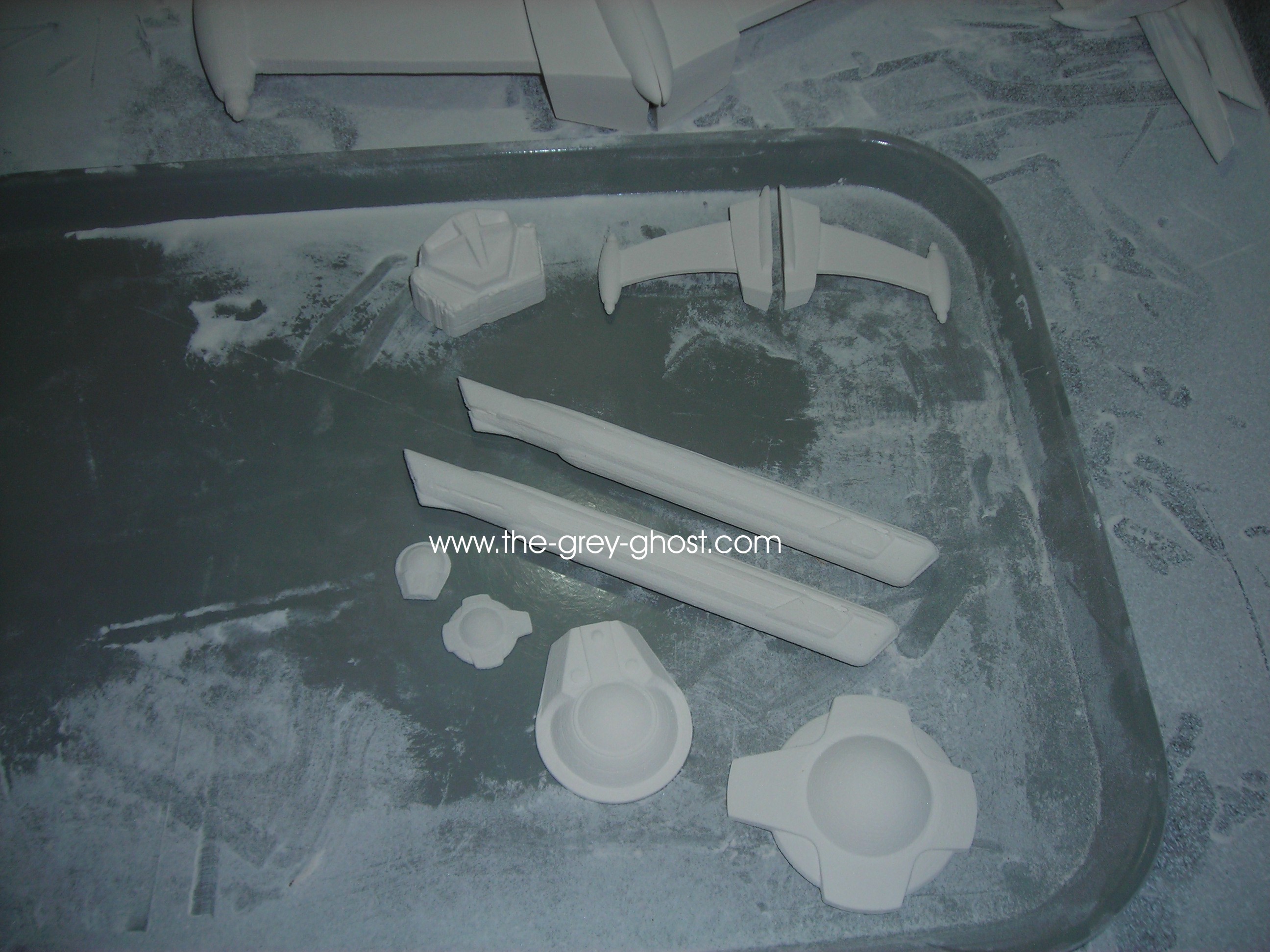
The bussard mount was printed, and here again is just set in place.

Here it is with the bussard ring in place.
And now to the other end…

The end-caps were printed along with the spacer below it.

Here they are together, with the end-cap ball sitting on top of the 2nd hull.

With the end-cap ball set in place. It likes to slide off so I have to be quick in taking pics. I did it separately to facilitate making the pilot versions.
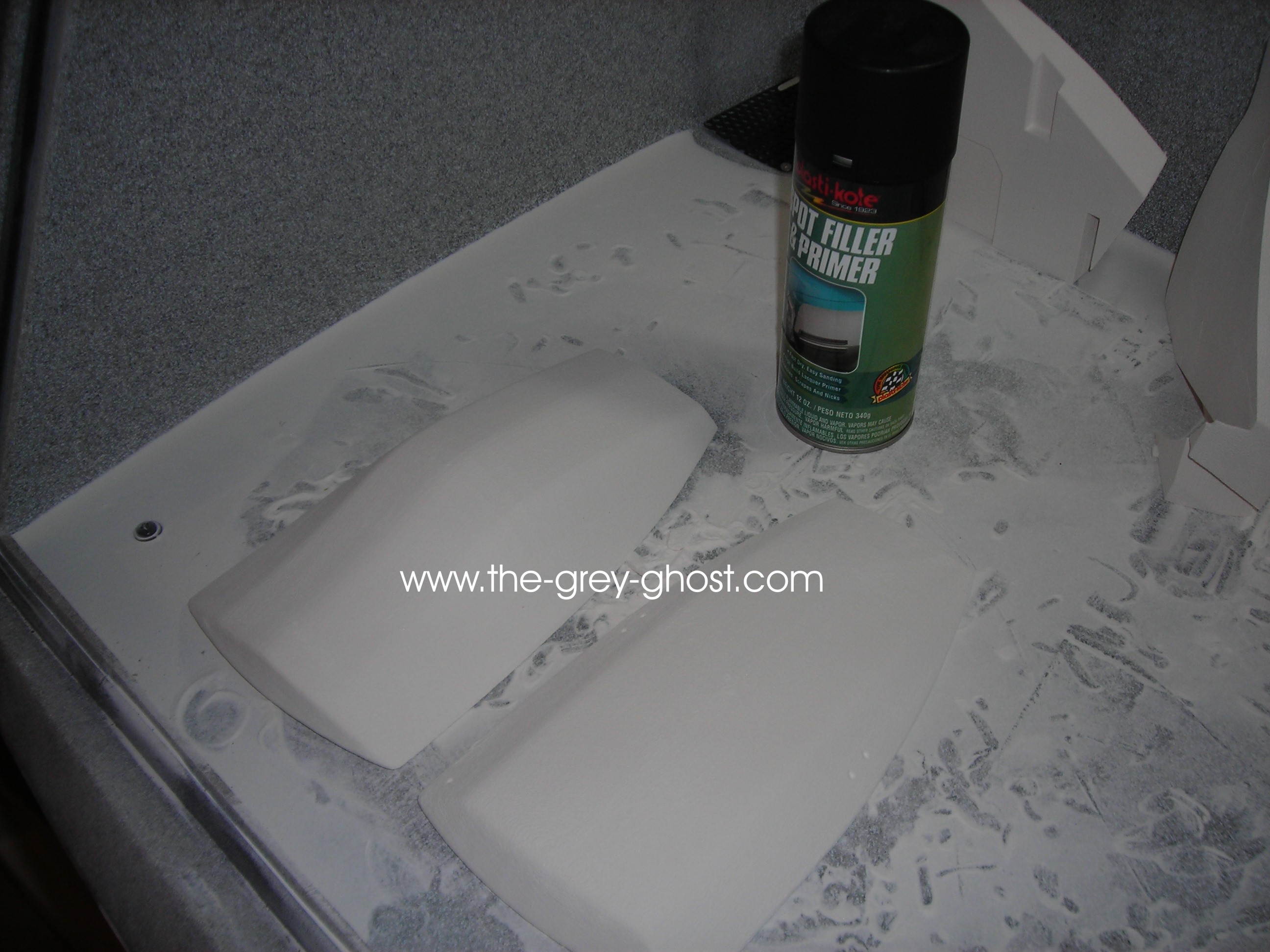
These parts still have to be cleaned up, which means endless hours of sand and fill, sand and fill, a little paint, sand and fill…

That’s it for today,

Posted 1/15/11

Proper(this guy was one of the reasons I left the boards) said: View Post


I may be the only one—and I do feel really stupid—but I’m simply not privy to the technology involved here that allows reproducing/scaling/sculpting with such accuracy! What is “printing”?

Don’t feel stupid, you just don’t know. And thanks for the question.

A lot of people have their own ideas about using this technology. They think it’s point and click, everything just appears by magic. It’s no where near that. To use these tools takes training, experience, and endless trial and error.

Before I can do anything I have to start with a model, namely a model created in the computer. Those start out as drawings in the computer.
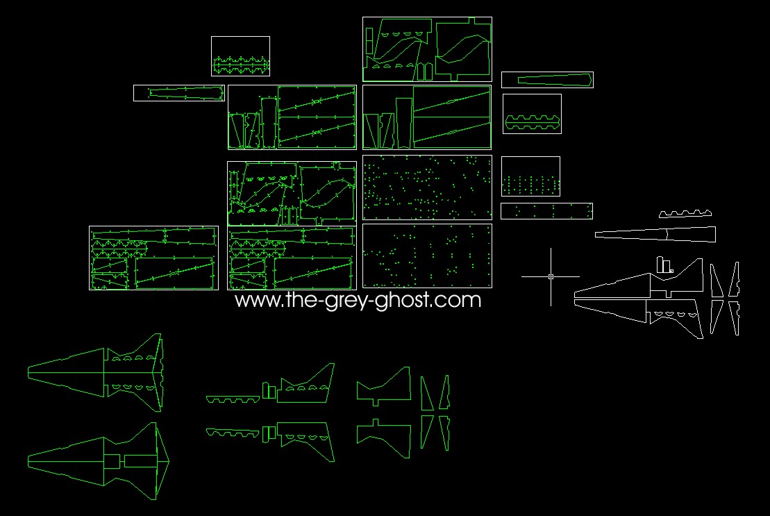
This is what started the whole thing for me(please forgive the image quality), These drawings were created by Alan Sinclair(wizardofflight) in Autocad. They were his take on the 11′ Enterprise. In my opinion they are the best that is commonly available(there are better drawings out there, I’ve never seen them, they are something that takes contacts to get. But his are real close, his parts almost match the JK 66″E & the MR E, I have both models and made comparisons to these drawings, I can’t say any of these are 100% accurate. Nor am I making any claims it’s going to be truly accurate, I’m just going by what resources I had access to. So no ultimate claims here).

I then take/modify these drawings to create a 3d model.


But that’s just the beginning of this process. Models such as this are useless in this state. It has to be broken down and simplified for construction. When I do this process I don’t bother with formal drawings, that would be a waste of my time(the only time I do it is with outside contractors).
The next step is to figure out what will be made with what process, and determine the internal structure. This process can take ages, and endless revisions. I can’t tell you how many times I’ve recreated the same parts. It’s like building a house, there will always be surprises along the way.

Once I have an idea of what I want to do, then the fun begins.
Take for instance the 2nd hull.

To get to this stage takes a lot of effort, it’s nothing like how the original was made. The original was a made of balsa planks and turned to shape on a lathe, the original was a one off, the guys that made it were on a budget and a deadline. Nobody cared how they did it, just that it was done on time and below budget.

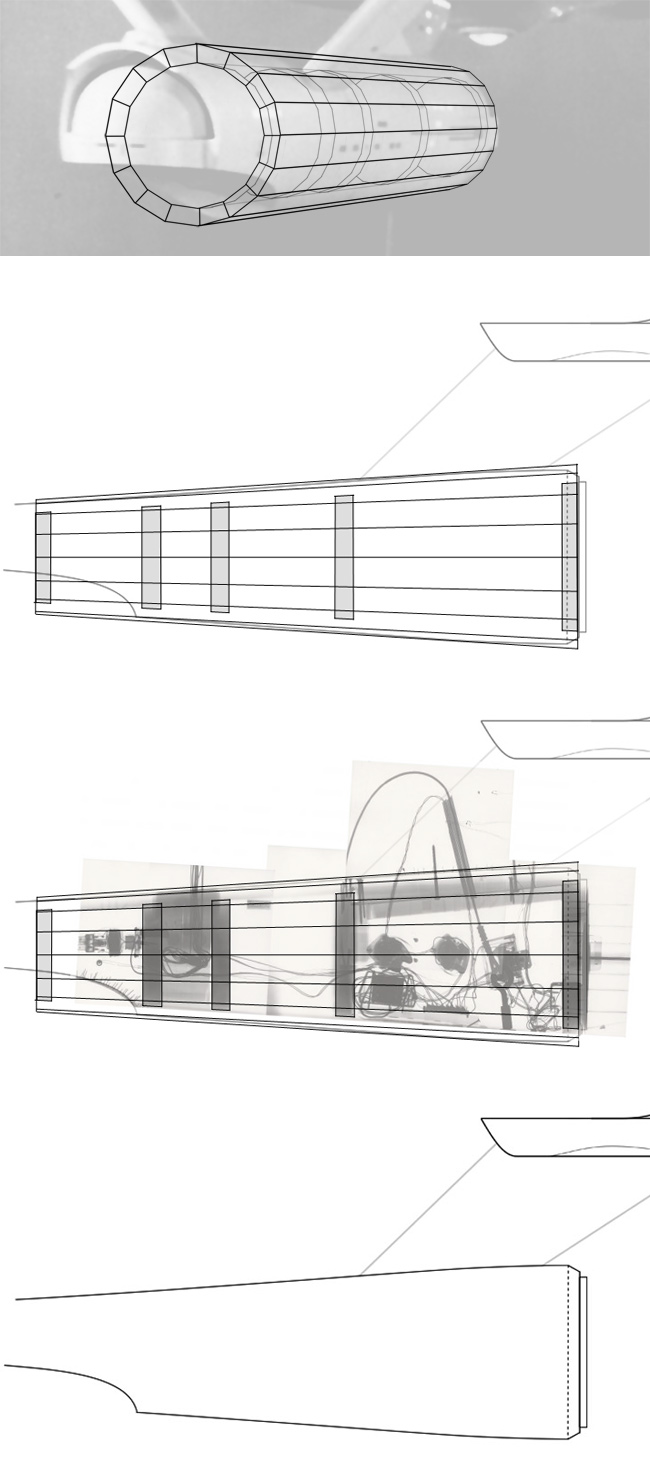
Where is start is with a profile.

This shows the side view of the 2nd hull. Since the hull is circular this makes things easy. Well easier than it could be. From this drawing I layout pieces that make the bulk of the part. I cut out each piece and laminate them to make a general shape of the part.

I then make a rough cut of the part below the final surface.

Here is the final part in RinoCam.

This is a wire frame model, this is what I use to create tool paths(it tells the machine how to move to create the shape of the part). That looks like this…

The software creates a path dividing the part into a series of profiles, in this case they are spaced in .01″ increments. This is(in essence) the same as the traditional method of setting profiles at regular intervals, and filling in between them, then fill & sand to shape. Using machines make that process much more efficient and accurate to the shape desired. BUT, it makes mistakes, and it’s leaves a surface that requires finishing(you can’t just put the part in rubber). If this isn’t modeling I don’t know what is, because I still have to do all of the same stuff I would with a resin model. I still use Dremels and X-acto knives on these parts, plus the sanding seems endless.


This is the part coated with bondo and being milled to shape(this can take several tries, to get right). The final cut for this part took over 30 hours. But the machine doesn’t need to rest, eat or take bathroom breaks.

3D Printing is very similar to milling.

This is my printer(the box to the right is the depowdering station), it is the same as a HP inkjet with a 3rd dimension.
Only it eats print heads at a much faster rate. It uses a powder as a base and prints a section of the part desired with a binder(it makes the powder stick together). Then it drops (.004″) spreads another layer of powder and repeats the process. The software screen looks like this…

This software turns a 3d part into a series of layers. Or sections if you like. The section being printed is displayed on the right. The software controls the printer, this is one of the easiest pieces of software I have ever used. But then what’s doing isn’t that complex. The milling software takes a lot more effort to get right. But then the printer can literally print any shape(withing the realms of physics).
Here is what the work area of my printer looks like…

It doesn’t have a very big capacity. So I have to make parts fit it’s work envelope(8″x10″x8″).
The fun is getting parts out of the machine. They are buried in the powder(and it gets a little messy).

This is the forward part of the Botany Bay(in the printer), scaled to my 66″ Enterprise.
This same model was scaled down to 350 scale and offered from Sovereign Replicas. The patterns were later sold and the same model is offered from Fantastic Plastic. These parts are in the depowder station, where any remaining powder in the parts is cleaned out. I use brushes and an airbrush, the depowder station is connected to a vacuum to catch and collect any airborne powder.

This is the 350 scale model, I’m showing these images to give you guys an idea of how this stuff works. I could literally make this model any scale at will. Saying that makes it sound easy, in some ways it is. But you still have to use modeling techniques after this stage. The surfaces show the striation of the building process, and have a very grainy texture. Plus they are not very strong. The parts are very porous I use CA to soak into the surface to strengthen the part. Then it’s back to traditional modeling again.

I hope this was informative, I’m sure I missed something, so please ask questions.

Posted 1/15/11

Aztek Dummy said: View Post


ATM,
This may be a stupid question (but that’s why they call me “Dummy”)..Is the powder re-usable? or is the leftover powder from your 8″x10″x8″ block like waste toner in a copier?

It’s not a stupid question at all. Like I said I do forget stuff. It isn’t like there are not a lot of steps to this process.

The powder used in the part is done, the powder around the part is used again. The powder is fed from a bin(the rectangle on the left) next to the build area, that powder is spread across the build area(rectangle on the right) with a roller(the polished rod below the black box on the right) , the excess powder is then dumped into a bin(not visible) on the other side of the build area. It can get a bit messy the powder goes everywhere.

Aztek Dummy said: View Post


Secondly, how to you figure in the thickness of the bondo layer when you are milling the wooden under structure? Do you make everything like a 1/4 inch smaller than the final size? then add 1/2 ” of bondo on top and mill that down to your final size?

I don’t, I guess a thickness of about 1/8″-1/4″ sometimes more. One of the problems of using bondo with this process is it leaves voids on the part. I’ve been getting better at laying up the bondo, but it sill happens.

If you look closely at the part, you will see some of the voids I’m talking about. It’s air gaps, and uncured bondo. That happens, using the methods I’m using it’s inevitable. If it’s bad enough I’ll re-coat the part, and run it again. I guess at my thickness to give myself some some room to run the part again If there are any mistakes. I have much more to show of what else I do to these parts. But I didn’t think to take pics, running these parts is so exciting it’s almost like Christmas morning when I get a part done.

Thanks again guys for your kind words, I better get back to the shop.

Posted 1/15/11

Aztek Dummy(Lou is one of the nicest guys in the hobby) said: View Post


thanks for taking the time to answer.The wood and bondo combination fascinates me. did you come by that combination out of economy or stability? I imagine you looked at a number of materials that would let you go straight to the finished shape in one step ( like that super dense material they use for sandblasted signage) or blocks of super rigid styrofoam. Or is it because the bondo lets you fine tune the finish with spot putty the best?See what you did? you let us geeks in on the process…there’s no way to cork that genie back up

I know, I’m one of you. I’m scary to walk around a store with, I know how they made almost everything. And there is no such thing as green manufacturing.

It’s a matter of both. Using a material such as Renshape would be great. But it’s expensive in the sizes I need, and there isn’t a local supplier in Phoenix(I couldn’t find one). The cost of shipping would get a bit prohibitive, and I need material right now. I don’t like to hold up the process a week while parts are being shipped. Then there is the waste, most of the material would be cut out in chunks or end up as dust. Using the method of laminating particle board allows me to create a base part with less waste and cost(and a lot of stability). I use bondo for for similar reasons, I can get it at Wallmart relatively cheaply, and it is very easy to work. I have at least 5 Wallmart’s within a 20 minute drive of my house. My wife likes to joke about, “El Tour De Wallmart”, yea she’s a cyclist.
Bondo can be a pain, and there is much better stuff out there. But the cost outweighs the convenience. Especially when I need a lot of bondo. Using glazing putty and high build primer is a quick and easy way to fill in the pin holes. These method’s were not figured out over a lot of trial and error. When trying to use MDF the surface was fuzzy, that could have been fixed with CA. But it’s a real pain to get smooth, and pricey. Bondo was the next choice for a surface. I stayed with that because each material has tricks to working it. I have ripped off the deck of my router when a cutter hung up on a bit of bondo. It can get pretty strong.

For me speed is most important, I hate to wait for anything. I had a business almost go under because subcontractors had better things to do than make money, and meet deadlines. That’s why I have the equipment I do, I like to get things done.

Posted 1/15/11

TheEmperorsHand said: View Post


Hey,What is your CNC router (brand name), or did you make it yourself?Thanks


I designed and built the machine. That’s a long process in itself, I made it with the help of a Bridgeport clone(a manual milling machine).

Posted 1/20/11

The low end printers have a long way to go, before they would be considered useful for the general public. People wouldn’t be interested in the machine unless it made items that looked perfect. Those days are coming, but when is anybodies guess.

Here is some more…

I thought you guys would like to see more process. The long two piece part is the accelerator, the one in Al’s documents was way off. That’s understandable it’s not that simple a part. I was really racking my brains as to how to create it.

Here is the original part, sadly it was modified from it’s original state. Why is anybodies guess, most likely to make the SSM follow a set of fan made plans(that’s what some of us think). This is the part I wanted to recreate.
I knew I was going to make the rail down the middle in styrene. So I sized it accordingly, to fit in a center channel. But I still had the problem of the rest of it.
That’s where this tool comes in…

This a 3D scanner, now before people start screaming digital recasting. It’s not that easy(I only wish it was). It scans to a maximum resolution of .004″, an object is placed on a turntable, and the object is traced by a laser. But since it uses a laser there is problems in the laser scattering(the laser sees best with a matte light gray surface, but it still isn’t perfect, I didn’t paint this part). And that effects the scan, which means a lot work on the other end.
Here is what the raw scan looks like…

This was scanned from a part I know is accurate, the reason there is blank spots is the laser couldn’t scan those sections. Because of the part’s orientation in the scanner. I took this file and opened it in Rino…

Above is a rendering of the part in Rino.


Here is the scan data next to profiles that were taken off of the accelerator. In this pic the contours look good, but they are not, and they have to be redrawn, which means things are going to change. Plus this part scan is useless to me, it would not sit on the saucer I machined(not without a lot of modification). Besides I only cared about the part profiles.
My goal was not making an exact reproduction of this part, but to make a new part to match my model. Since the profiles were incomplete I filled in the missing sections.
Here is the completed part in rendered in Rino…

See how it doesn’t look quite right, that’s a remnant of tracing the contours. Really I could care less, because I’m going to fix that in the printed part. All I needed was something to work from. If you look at the printed part it does look a little wonky. It’s nothing that a bit of sanding couldn’t correct. Another thing I did was rescale the part for the model, the part I scanned was about half the size of what I needed. The printed part was split so it would fit in my printer.

Like I said I was only after the part’s contours, I hope I have shown that it isn’t an exact copy of the part. I do not condone recasting, the idea that you can use my scanner to make an exact copy of a part is nearly impossible. I couldn’t get that good a scan off of a part. No matter what I do I still have to recreate what I’m scanning. Which means it’s going to change. I have directly printed parts from my scanner, normally it has very poor results.

To answer the question of where I put these parts. The printed parts are in my modeling room, the routed parts are in my garage(they stand easily on one end). Right now I’m rearranging my garage for this project. Lucky for me my router works on it’s own, so I’m free to get other stuff done.

One other thing, Bondo is really nasty stuff, a router can be a better dust producer than sanding. My machine is contained and I have a exhaust system. Anybody using my techniques use with caution. I can’t take any responsibility for what someone else does.

Posted 1/20/11

This is the sort of thing that make projects like this very satisfying.

The parts are taped together to check fit. I set the bussard mount in front to also check fit.

The bench I have it on is a little bowed. I assure you They match.
Why am I showing these now, because I couldn’t stack the parts in this manor before.

Note the stacked pieces of particle board and MDF. One of the tricks I use is to add an extra board under the part. It gives me some breathing room when creating the part. As well as some additional clearance, the reason it’s there is allow a tool I have to cut undercuts around each of the parts.
That gives me an edge to match the parts, But I have to mill off the additional wood below the part line. Sorry I don’t have any pics of this process. I’m sure you guys will get the idea.


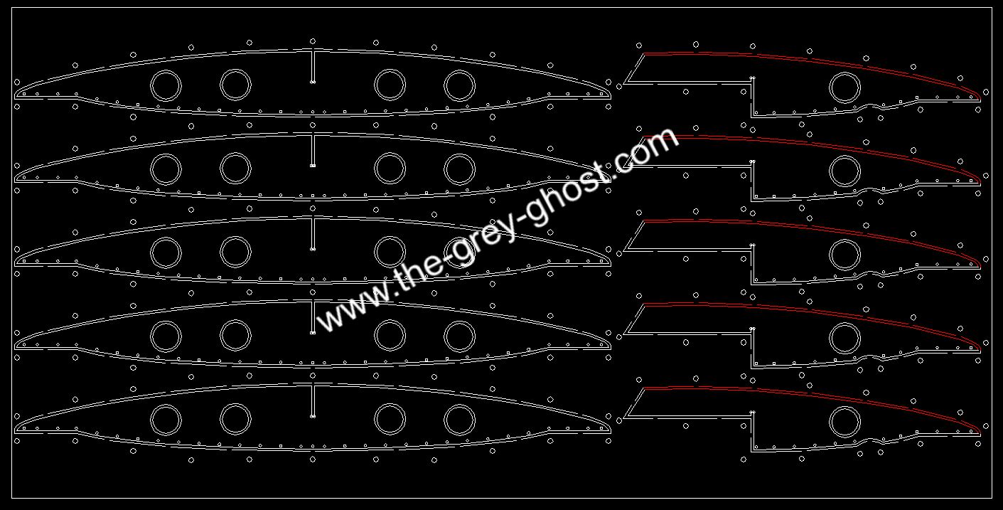
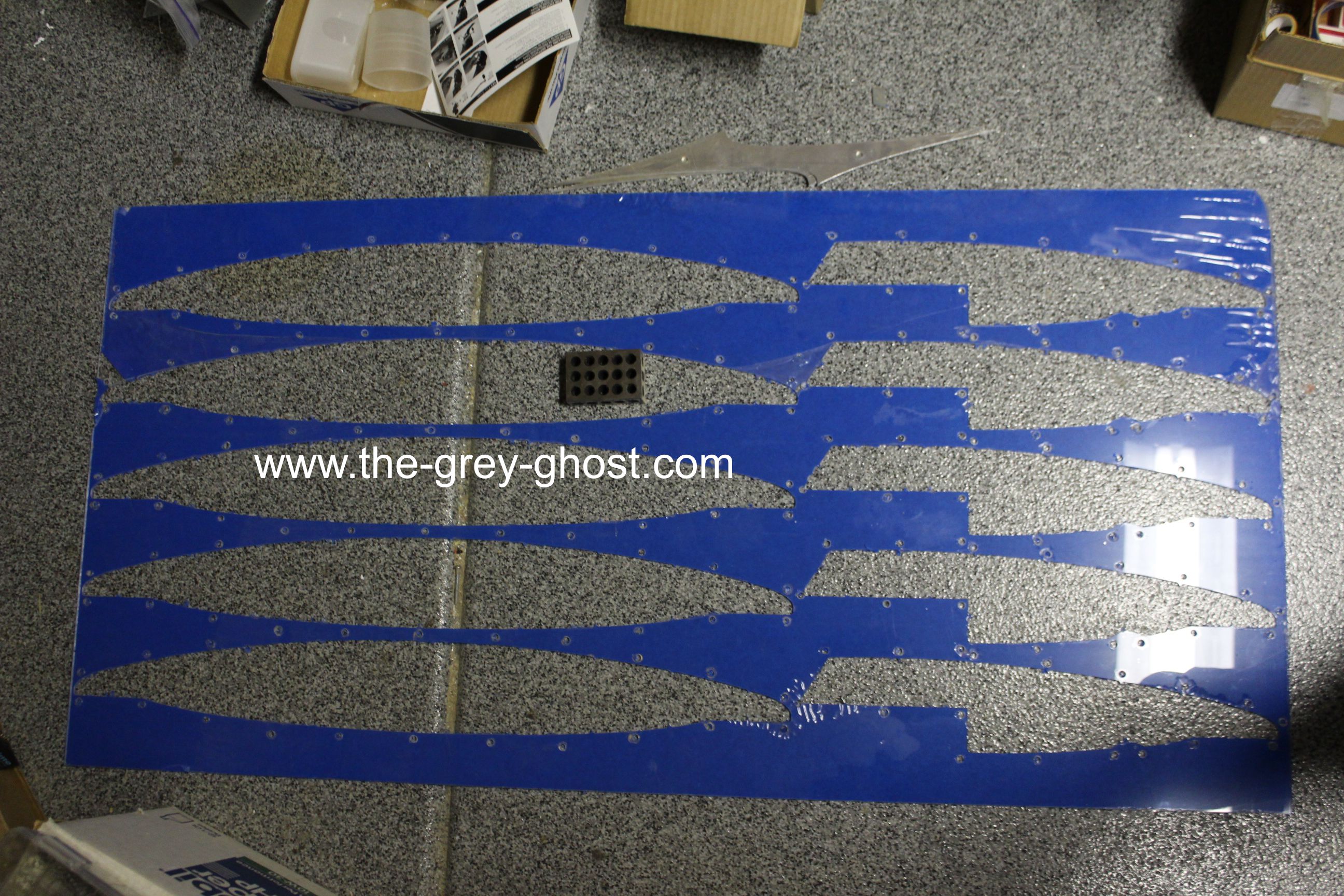
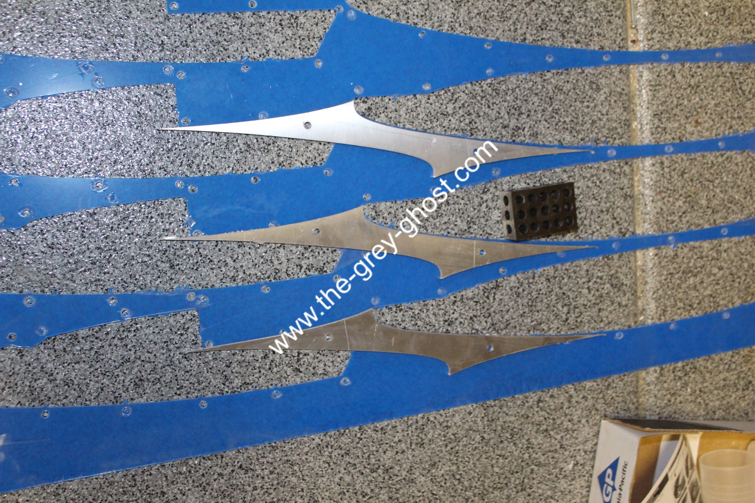
These are the molds/jigs for the pylons. Note the rectangles at each end. Those are there to place the 1″x3″ aluminum tube, it gives me a length, and sets the parts in position. The pylons themselves will be made out of fiberglass, since the weight of the nacelle will be carried by the aluminum tube. One other trick I did with these is to mill in the profile that matches the hull and nacelle. Which is the channel between the rectangle and the pylon. When these parts are finished the pylons will bolt into the armature.
I’ll show that when I have the armature done.


This is one of the bussard collectors. It is the pilot version, since it has a flat spot to accommodate the spike. It still has to be finished, I haven’t made up my mind whether to make this one out of fiberglass, or blow mold it, or vacuum form it(I’m leaning toward blow molding). I did drill in an 1/8″ hole in the center since I took the pic. I’m sure you guys will see these molds again.

Now while the router is running, I’m not sitting idle.

I was working on this, the pic looks great. But you can’t see all the pin holes I have to fill. But I did eliminate the tooling marks(groves left by the milling process). It still has a way to go before molding and I still have to add the sensor bands.

That’s all for today.

Remember if you guys have any questions ask away.

Posted 2/3/11

Here is another update.

All of the big parts for the E have been machined.
Now for the fun of fitting and finishing the parts.

My router plays a role in this.

The parts are a profile and a cradle for the secondary hull.
I did the same thing for the engine.


here is one half of the hull in the cradle. This makes things easier to handle, and helps to protect the parts. Each of the parts that cradle the hull are a 1/8″ larger than the parts they hold. This allows some room for padding after the hull has been finished.

The cradle that’s more impressive is the nacelle cradle.

It plays a very important roll, since the nacelle is in 4 parts. The parts have to be aligned for mating. Note the steel plate the cradle is sitting on. It’s 3″ thick 2′ wide and 3′ long(it’s about 600 pounds). It was from a machine I designed that didn’t work, but some of it’s components come in very handy. This plate is precision ground, that means the surface is really flat. Not perfect mind you, but more than enough for model work. The slots in the plate are called T-slots so I can bolt things to the plate. The plate and the cradle work together to help make things straight.

I don’t care that the cradle is hanging off each side(besides I couldn’t help it). As far as alignment goes it’s fine. Note the line of MDF between the nacelle half’s. That is what I use to match and eventually mate the parts.
This is what it looks like.

It has a series of holes for pins, each piece of the nacelle has these holes. I use them to align parts in the router, as well as for this purpose. It saves a lot of time, and headaches especially when things go wrong.

The 2 slots in the middle of the template are there so I can route(using a hand router) channels for steel bar to mate the halves(I haven’t done that yet).


Here is a close up. The parts are just set in the cradle, the alignment is very good.
Here is one part of the trick to getting a good alignment.

There are tabs at each end of the cradle. These allow me to place the parts right where I want them, then the template will do the rest.

I did start working on mating the neck to the second hull.

I figured you guys wold like this view. It’s hard to use a camera with one hand, and try to get a good shot.

That’s it for this update, I would have had more done if things were not so cold. Phoenix has been down in the 40’s which makes my garage feel like a meat-locker. For Phoenix that’s really cold, but then to my thin blood anything below 70 degrees is cold. Before I hear people say that’s not cold, keep in mind our summers can get above 120 degrees. It’s all relative.

Posted 2/8/11

As a friend pointed out, I plan everything. Something which this hobby isn’t known for. I consider this a design project which means I have completed the design before I get to the machining stage. The armature to me is the most important part of the design. You can do almost anything with cosmetics, but a bad structure makes the whole thing a failure. If the model starts to sag in a few years, then it’s a waste of time.

SteveNeill(a friend to this day) said: View Post


Do you plan an interior support structure for the eventual (I assume) epoxy glass model?I question if it’s necessary for my smaller 66 inch version if I build the secondary hull and pylons from thick layup Matt and a light layup for the saucer and nacelles with glass cloth.I suppose in terms of engineering and structural strength size does matter. Meaning a small 1/350 model needs no such support but as the size increases and the mass – weight it does.

Certainly at the original 11.5 foot it will?

Steve

The model is going to be a fiberglass shell with an aluminum armature. On your 66″ your going to need an armature, the 66″ I have has a 1/4″ acrylic armature in the secondary hull and saucer(A 66″ model is a good sized model, even using acrylic may not be enough). The pylons are resin with an aluminum tube cast into place. But they rely on the fiberglass of the secondary hull for support. That’s a real weak spot, because the glassing work on the model is suspect. I have parts changing shape on their own, so even after I complete that model I will be looking for problems.

The structural problems with the TOS E design are complex but not that complex. There are two critical areas on the model.
The white arrows on each end of the model signify gravity. See how far they are from the secondary hull. These cause stress on all of the points I have circled. The primary hull isn’t that hard because it has a lot of room for structure. But the engines pose bigger issues.

The spindly pylons(I think they are a joke) are a problem because they would twist about their base. If you used a weak material without any additional support. Or put too much weight into the nacelles. You’ll eventually have a really warped ship.
You’ll have to do it Steve, or you could do what the other guy did that made a 66″ E, hang it from the ceiling on strings. He’s not going to be very happy with his ships down the road(if he isn’t already).

My pylons are going to be a fiberglass shell, with a 1″x3″ aluminum tube for support. Those are going to bolt into the 1/4″ aluminum armature in the secondary hull. This is where things get interesting.


This shows what I’m doing in section. The pylon support slides into slots milled into aluminum plate. If you’ll notice the rectangular slot in the secondary hull plate. It(there are 4) will slide into corresponding slots in the armature of the 2nd hull. That’s so I don’t have to weld anything, they will just set in place with gravity’s help.

All this why there is box shapes on each side of my pylon patterns.

So the parts will be the correct length, and correctly positioned within the pylons. This structure prohibits a shuttle bay in the model. Since I don’t know how far back it goes into the hull, I’ll bet it would interfere with the model’s structure. As well being able to break down the model should it need to be moved.

I would follow similar rules even with the 350 version of the ship. But that doesn’t mean using metals, but since metals are relatively cheap for such a small model it would be a lot easier to epoxy into place.

Aztek Dummy said: View Post


ATM,
I very much like the idea of the cradle you have for the secondary hull.You should give serious consideration to making it the stand for whatever kit you come up with as a result of your efforts. perhaps made out of clear lucite or other such material, but I think it would be much more preferable to the “ship on a stick” pole type stand

I’m doing just that, it will be a ship on a stick. But 1″ the stick is a 1″ steel tube with a 1/2″ center(for electrical). Keep in mind the amount of force required to make the steel bend is so extreme, you could pick up a full size pick-up truck, and the bar will only deflect slightly. That will be going into an aluminum armature.

A cradle is not practical for display purposes and it would pose additional problems(the cradles I made are for matching and finishing purposes), plus it wouldn’t change anything in the structure of the model. And it would have to still have to be anchored to the model. The shell of the model will be supporting very little. It would really detract from the look of the model, as well as having a very awkward base. I have that designed as well, it will be a piece of furniture(on casters). So I can display more things below the model. And keep the model high enough to be able to walk under the primary hull.

Here is a rough sketch of the armature in the 2nd hull.

This is very rough, I’m still working on the details. There are a lot of them. Such as the 1″ slot in the bottom, that will be a tube for the model to set on(with set screws), the wiring will run out of the tube into the hull. It would be impractical to have a connection like the MR E. Since this isn’t a model you can fly around the room.
It does show what I’m thinking, and there is another point of trouble. That is the connection to the primary hull. Other models(the MR E & jk 66″) you cannot remove the primary hull from the second(not without a lot of work). On this model if I couldn’t remove the the primary hull, it would be very impracticable to move(or ship for that matter). I have the solution but that will have be to another post.

Questions? Comments?

Posted 1/10/11

Here is the Original E-

The stand it sits on tells me there might be some issues. But it has stood up well. Considering it wasn’t built to last(just through the series photography), nobody expected it to still be around after 47 years.


That solid hull is why the windows below and forward of the pylons were not lit.

Making things solid is not always a good thing. Even solid objects can deform over time(I’ve seen stone columns bowing outward under a load) . It’s best to keep things light as possible, with a structure that has more strength than you would ever need. And in the case of this type of model you need to gain access to the interior. The last thing you want to have to do is rebuild a portion of the model just to change a burned out light.

I’m not worried about the stability of the structure, since I’m using aluminum it would be very stable. Now metals can flex, but since the model will be made of fiberglass. It would be nowhere near the weight that would make the metal flex. Plus fiberglass can be layered up to be very strong(even stronger when bonded to the aluminum) and it only has to support itself. All of this I considered when I was designing the model.

It’s my hope that some of you take this info into consideration with your own builds. Whatever subject they are, I assume you guys are like me. When you build a model you want it to last.

Posted 2/10/11

This was posted by Shaw, I’m including it because it’s interesting and on topic.

While the supports and dorsal were solid, the secondary hull wasn’t. It was built like a barrel, with open cavities inside. The reason for the lighting being the way it was was because they cut holes in the front and back to access the forward most and rear most cavities. All the wiring between was taped to the outside of the hull until the model was modified to serve as a display piece.

This is approximately what the unturned barrel structure look like…

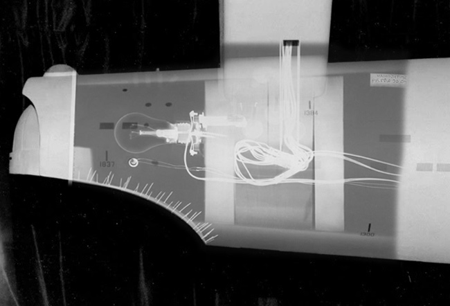
As for the strength and longevity of the original model, for a good portion of it’s life it was hanging rather than sitting. In that hanging position, the weight of the model was supported via points on the nacelles and the dorsal (though most of the weight was carried by the dorsal point).

Before the model was modified for the second pilot, the model was filmed hanging from a single wire that passed through a channel hole in the dorsal to an anchor point at the bottom the the front cavity of the secondary hull… a point that still exist today (and can be seen in the x-rays of the model).

Of course none of that has any baring on this model project.

But one thing you might consider… the way the original model’s nacelles were built, half the weight of them was originally in the front third of the nacelle. They were almost balanced about the point where the supports attached to the nacelle. So having hollow nacelles might not be enough, you might want to add weight to the front end of them to help keep them true.

Posted 2/10/11

More from Shaw at my request.

Atemylunch said: View Post


Shaw can you superimpose the current support in relation to the x-ray?

I have this smaller one (of the aft end) done…

… but I think I have a nice enough side view of secondary hull that I can do the full length x-ray in a little while.

feek61 said: View Post


Also the starboard nacelle is lighter then the port nacelle. It does not have any of the inboard detail (since it was never seen on camera) as the port nacelle which apparently causes the port nacelle to sag due to the weight.

In addition to this, I think the weight balance was thrown off with the removal of the original wooden domes and the hollowing of portions of the front third of the nacelles for the series.

Posted 2/12/11

Now I thought the ship was more or less unmolested, before the re-imagining.
Ed did do more to the original model than butcher the paint job. He changed things out right.

Such as-

Now one might say this is minor, but in a purists book this is a big no no.
A part was altered from the original. You can argue people’s theory’s all day, in reality he did what he wanted. The paint job proves it. I’ll bet he was far more happy to be paid for the job, than any love of the E. Model builders in Hollywood are/were not paid all that well. And any boasting rights mean everything, because it means your next paycheck.

In this hobby you can’t take people at their word. Just because it’s published somewhere(especially around this ship). Keep in mind the guys that made this ship looked at it as a job. That job was about 47 years ago, memories can fade even after a few years. The only thing we can rely on is the photographic evidence, and the model itself. But if the model is altered, then things get real murky.

Posted 1/12/11

SteveNeill said: View Post


Plain and simple. I agree. Very wrong to do!Steve

And it’s unnecessary. If he did a straight-up restoration(no access weathering, etc.), and charged the same amount of money. It would have taken less time and he would have walked away with more money in his pocket. Plus it would save having to suffer endless years of grief, from ST fans and model builders alike.

Posted 1/12/11

Funny how there isn’t any sign of panel lines on the nacelles, 2nd hull, lower saucer. Thanks Spockboy, I always thought the same thing. The ST exibition that came to Phoenix was very very(I asked for my money back) disappointing.

I see this is your first post Spockboy, welcome to the RPF.

Now another update.

You guys remember me showing you this.

If you remember those slots in the middle.

I routed those out today, and put the nacelle together.

Here is how I did it-

I cut a 1″ steel bar to fit each of the slots(they are 12″ long). I use steel because of its strength, and hopefully it will not flex(it won’t at that length, and the application isn’t strong enough to be any problem).

But I do need to drill holes for screws.
So I use my trusty milling machine.

Pardon the mess, this is a manual milling machine. To some it will look like a drill press on steroids. It does do a whole lot more than drilling holes. It weighs over 2000 pounds, and is precise enough to put my initials on Lincoln’s eyeball(on a penny, I’ll never do it. I can’t see that well).
It’s main job is to use a cutter to shape any material(looks like a drill bit, but it can cut on the side of the bit. They are called endmills, and they come in a variety of shapes and sizes. I use them in router as well. I’ll show more about that as the project progresses). It is an indispensable tool in any machine shop.

For this post I will be using it to drill some holes.

Now in this pic you see a vise(blue thing to the left), a drill chuck w/drill bit(top). Below the drill bit there is a steel bar with holes in it. Now I needed to drill six holes in four bars. Some will think that could take all day. Nope it’s whole lot easier than you think. The first thing I do is mark where I want the holes, I’m not showing that because the holes only need to be close to where I want them. Once I figure where I want them. I put the bar in the vise(tighten down).

Before I drill the hole I do something else.

See that little red box with the shaft on the left side of the vise. It has many uses(I use it hold measuring devices, at times), it has a magnetic base so it can be moved around. In this application I’m using it for a stop. It’s placed at the end of the bar so I can drill holes in the same place on each bar. And since I need holes the same distance from each end of the bar, I just flip the bar over and both sides are taken care of. It really is that easy, and you can do the same trick with a drill press.


Next I place the bars in the slots. The fit is excellent.


Here is one side of the nacelle with the template removed, and the bars screwed into place. The nacelle is now one piece.
Next-

I place a pin at each end. So I can put the nacelle together for sanding/matching.

I placed an end cap on each end of the nacelle. So I can keep things together. It’s notched so the cap is centered.


Here is the Nacelle in one piece. I have started to sand and it will take some work to get everything right. It’s fit is much better than some mainstream kits I have.

That’s it for now, any questions comments?

Posted 1/14/11

Here is another satisfying afternoon in the shop.

Again pardon the mess, that’s what happens in my shop. Especially when using hand tools. Most of you know the 2nd hull of the E, I put it together with the same technique as the nacelle.

With one exception, no pins, I had to do the old fashioned way. The parts were off when I machined them, so I couldn’t use the pin trick. That’s more of a convenience, the parts were fine except for that one flaw. So I use the templete to align the 2nd hull to the neck. If you look just to the right of the bars you’ll see some chrome disks. Those are washers I place those in key spots so I can match each side of the 2nd hull. I placed those along the spine and the front of the hull. Then route out the groves for the bars.

Here is without the template, there is a gap between the parts. I’ll fill it in with bondo later, the only thing I had to be careful of was using screws that were to long. The neck isn’t all that deep, I did break through a few times. That’s not a big deal at this stage. Nothing filling and sanding won’t take care of.


I figured you guys would want to see these parts together. If you look in the middle of the image there is a 1-2-3 block there for scale.

Now onto something else you guys might find interesting.

Here is the upper saucer, I ran this part back in October.

I wasn’t entirely satisfied with it(you guys know how that gets). So instead of spending endless hours trying to get it right. I’ll run(machine) the part again. So I have my router place the part’s locator pins(that’s drilling holes). I do that so I know where my origin is(0,0,0 that’s so the router can machine over the original part without cutting into the original surface), and place the part in the machine.

First step-

Re-coat the part with a thin layer of bondo.

Next-

Machine the part, I did what is called a rough cut(at .03″ spacing, it took the machine about 12 hours). It’s the first pass to see how well I coated the part, and to catch any voids and major pin holes. The red marks in the part are voids.

Next-

I fill in the voids and large pin holes with bondo. This time I’m trying something different. Since the part has an endless number of pinholes, I figured I would try glazing the part before the final pass. Just to see what would happen.

Well…

I started running the part this morning, this is what it looked like in the afternoon. All of the red dots are pin holes. Here is is a little closer.

Kind of interesting to see just how many pin holes there are.

My machine is running right now, and it will run well into tomorrow. The final pass I’m running is going to take well over 33 hours to complete. Why? You ask, well I’m running a very fine spacing .01″. That’s one hundred passes for every inch of the upper saucer. The reason I’m doing it so fine is so there is less work later. It means less sanding and (hopefully) less filling in pinholes.

To be continued…

Posted 2/17/11

SSR said: View Post


With technology moving forward, we might see some of what you are using in a home shop environment yet.

Funny, my shop is in my garage.
The hobbyist CNC market is very well established, and it’s amazing what some of those guys do. It takes a little knowledge, a lot of work, and a great deal of desire.
But if your looking for the easy way to do this stuff. This isn’t it.

Continuation…

I was last machining the upper saucer, things were going well until…

About midway through the job the router drops. Why I have no clue, but it’s cutting below the surface I want.

This happens every now and then(most of the time it goes up), the router will do something like this, then go back to cutting on the original plane. Most likely it’s a software glitch, after all the code to run such a part has hundreds of thousands lines of code. There is bound to be some problems every now and then. Now I don’t consider this a big deal, but it does mean creating a new tool path(this tells the machine where to cut) and reapplying bondo.

When I make a new toolpath, I change it’s spacing. In this case I tell the machine to cut at .02″ spacing, that’s 50 passes per inch. It took less time(about 17 hours).

Things went fine this time. I’m happy with the results. Then comes finishing the part for casting.
I’m sure some of you are asking why I do things this way. The main reason things like this are done is to make the next step easier. The part will take a lot less effort to get smooth than if I made the part by hand.

Posted 2/24/11

spockboy said: View Post


When I heard CBS Digital was re-doing their cartoon FX for TOS I was hoping against hope that they would have someone like you build an 11 foot replica. Can you imagine how good it would look with today’s film technology?
It would look huge and colossal.

Sadly that would never happen, most likely Hollywood would never go back to exclusive use of miniatures.

That brings up a question for some of the special effects professionals we have here.
Why did they build such a large model for STTOS?

Posted 2/24/11

-Posted by Robn 1-

KUROK said: View Post


I suppose so they could get it all in focus as a small model they’d have to get closer?

Keeping it all in focus is the main reason for the model’s size. That requires a strong depth of field, to keep the close end as sharp as the far end. Lens capability dictates the model size. Advances in lens technology allowed smaller models in later years. The Enterprise really wasn’t unusually large for the time. In 2001 the discovery was 54 feet, by the time 2010 was made they could get the same effect with a 12 foot model.

Posted 2/24/11

-Posted by Shaw-

And because the 11 foot model wasn’t ready for most of the effects shots for The Cage, we can compare how the 33 inch model looked in camera in 1964 with how the 11 foot model looked in 1965 (making a similar pass)…


Posted 3/21/11

Yes, I’m still on it. But it’s at the stage where I’m doing the filling and sanding.

In case you guys haven’t seen these-

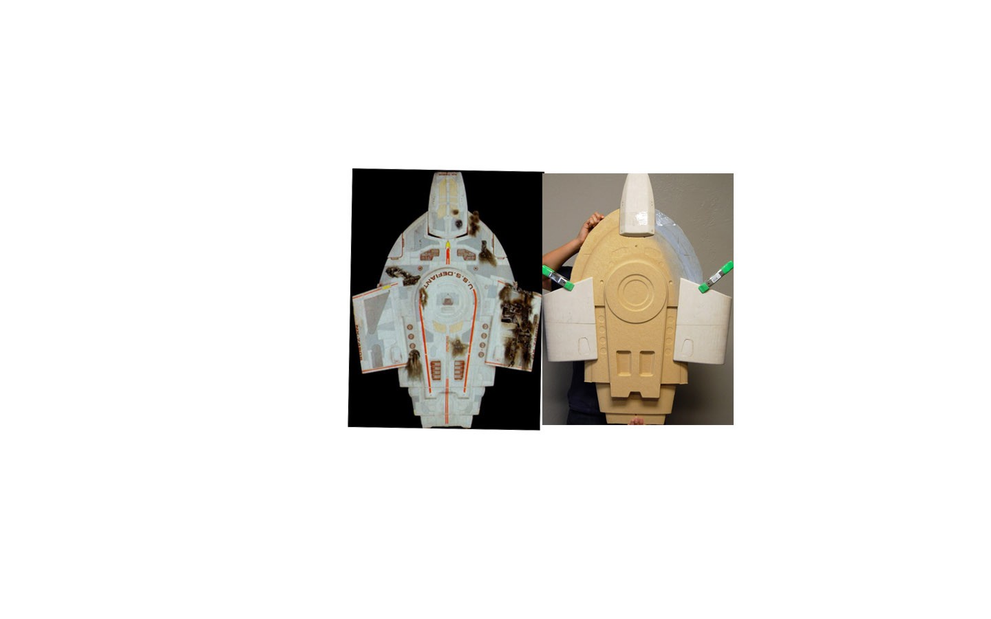
Here is the Custom Replicas 66″ nacelle on the studio scale nacelle.


Here is the 66″ upper saucer on the master for the SS upper saucer. This is where I’ve been dividing my modeling time. I’ve been posting it over in the general modeling section. Under the thread-
http://www.therpf.com/f11/custom-rep…-tos-e-110204/

I did have to make a new endcap for the nacelle.

This is the rough stage, the one on the left has been routed to a base shape, the one on the right is just the particle board stacked up.


The one on the left is nearly complete, the one of the right with it’s second coat of bondo.

This is where I have stop with the pics(because I don’t have any more), both parts are the same. I’m going to vacuum form styrene over these parts so it will be easier to attach the corrugated material to them. And save me some time finishing the endcaps.

I’ll post new pics as soon as I have some more progress.

Posted 5/5/11

Don’t worry Spockboy, it’s continuing.

I’ve been prototyping the armature.

I made this out of 1/4″ MDF. I did it to experiment with the design. The final will be in aluminum, this is a far less costly way to figure things out.


This is what I’m thinking of doing in the warp nacelle.


These are not finished, I still have a lot to do. Remember these are for prototyping only, the final model will have an aluminum armature.
If you look in the background you’ll see the Big E’s parts everywhere.
I’m fixing those parts so I can wet sand them. Particle board and MDF doesn’t do well when soaked with water. Then it’s back to paint fill and sand.

I’ve been working on other stuff as well, my little E(66″) has been taking a lot of time and frustration. I’m doing stuff to it that will make it a very interesting model.
Plus I’m prepping a blog for these builds for better exposure. I’ll post that when I’m ready, besides most of what I’m putting on it right now you guys have seen. It does need to catch up to this thread.

That’s where I left it.

You guys will love this, I since started the whole thing all over again. I got accurate info which made me rethink the whole project. Things are going to get much more interesting from here.

Studio Scale Models, Studio Scale TOS Enterprise(11.25 feet)

The Wonders of Star Trek: The Transporter, Part Two

In the last article, I talked about the basics of the transporter(MTAMS) and what they would do with it.

Here is some more of what they would do with such a system.

Imagine a world where you could make anything. Materialism wouldn’t be the same thing as in our world. Before you get outmoded ideas of socialist utopia, where there is no money, and all wants are fulfilled. That idea never worked, there is always a price, always.

In the case of MTAMS the price is energy, which would be the base of a means of exchange. What would stop everybody from making whatever they wanted(their own starship?). Quite frankly the waste of such a society would make what people complain about today, look like nothing. But one thing such a system can do is turn such waste into anything else.

So any matter can be manipulated into something else. Thus the ultimate form of recycling. Unlike in our world, where the only thing that is truly recyclable are metals.

Metals are infinitely recyclable, they can be melted down repeatedly. Where other materials such as plastics are very limited in their reuse. But under MTAMS it uses atoms, so as long as you have atoms and energy available the system will have something to convert.

Like I said energy is the cost of using the system. So a society would need to have a form of monetary exchange around the use of that energy. Or more simply put, you need to pay for the energy used to make what you wanted.

Of course you could create your own reactor. I’ll bet in the Star Trek world things would not be that simple. Creating such a system would be the easy part, running it is another matter entirely. The reason is simple, such a reactor would be so powerful it would make Sol look like an single LED(light emitting diode). Could you imagine millions of such reactors all over the planet. Such things would have to be regulated, since one mistake could mean a very bad day for everybody.

If a reactor goes critical an explosion will most likely not happen. If reactors have problems they don’t normally blow up. They melt down which is a whole lot worse, but that’s not as exciting as explosions.

One other thing to consider is how such a system would effect the value of everything. Take a rare piece of art, if you could recreate the artwork to the finest detail. Then what value would the original have?

None, unless measures were taken to protect the art. Even then who is to say someone wouldn’t switch out an original. Not tell anybody, so everyone assumes it’s the original piece. So you can see this would be a real problem. But the upshot is you can have any of the great works. Without the high price-tag.

There is a lot more to this, but I feel it’s best to keep this on topic.

Namely how would such a system be used to create another wonder of the Star Trek universe.

The Starship.

When spending a lot of hours working on this subject, I can’t help but think about how would they build a starship?

Sadly most people try to place these ships in the same context as we build ships today. That’s like asking someone from the 1600’s to conceive and build Concorde.

We really have no idea of how a ship capable of faster than light travel would operate. Someone from the 17th century wouldn’t have any concept of aerodynamics, jet engines,  avionics(much less electronics), and the materials and methods to make the shape. It’s quite a list.

So all we can do is guess, and have fun with it. Which is why I’m writing this.

Starship design is more or less wide open(as long as you have at least two nacelles), but with the MTAM system. You can see what would work relatively quickly and be able to correct any issues. (Even in flight, I’ll get more into that later).

To use MTAMS to build a starship you need several things.  First off space, raw material, and a lot of power. Nor can you forget the people involved, but that’s another story. I’m only going to focus on how they would manufacture a starship.

The first thing to consider is a location for the shipyard. Now using an MTAM system requires two things raw material and power. Both of these requirements would limit the locations of such a shipyard.  The last place you would want such a shipyard is in orbit about an inhabited planet. Which goes against where Star Trek lore was placing them.

Why not in orbit about a inhabited planet(especially the seat of the Federation)?

Engineers are a very cautious lot. They don’t like things going wrong, but if they do best to minimize the damage to life, limb and property. Especially with the potentially large part designed for deep space travel, that would not break up in an atmosphere. It would leave a very large crater upon impact, or if it did break up, it would leave a lot of little craters. Either way the results are not desirable. In tribute to Murphy, “Whatever can go wrong, will.”

There is a second thing to consider, the reactors used to generate the MTAM process. Each reactor would be far more powerful than Earth’s sun. Like today’s nuclear reactors(at least in the US) , there would a number of safeguards to prevent catastrophe. Engineers being engineers would insist upon a more remote location, than the seat of the Federation.

The other thing is raw material. Raw material can get very expensive to move around. Especially when you need a lot of it, and a steady uninterrupted supply. If you had to move the material from one place to another, lets say to another world. That compounds a number of issues, as well as being unnecessary.

So we need a place that is secluded with a lot of raw material. But not too far away to make it prohibitive to travel there.

Is there such a place in our solar system?

Yes there is, at least two that come to mind. The first is the outer solar system beyond Pluto, there is a large amount material out there. But it isn’t as desirable, due to it’s distance from the inner solar system. Plus the amount of matter may not be as concentrated(we can only guess). The other is obvious, the asteroid belt between Jupiter and Mars. It meets all our criteria, and it’s only a few light minutes from Earth.

So what would these shipyards be like?

Not like anything we do today. There wouldn’t be any welders, plate metals or even large cranes. The shipbuilders of the future would look upon our methods of construction, as we would looking back at the construction of the sailing ships of the 18th century.

So if they are not carving or building sections and assembling them, just how would they do it?

The answer is obvious, but I will save that for the next post.


Off Topic

This says it all

Neil deGrasse Tyson at the Starship Smackdown, Comic-Con 2012

Thank you Neil.

Studio Scale Models, Studio Scale TOS Enterprise(11.25 feet)

The Wonders of Star Trek: The Transporter Part One.

The creator’s of Star Trek made that universe, so what happens if you apply those ideas to our world?

Things get interesting, real interesting.

So what do I mean by this?

To use our civilization as an analogue, whenever we come up with a new technology or application. We look for all of the ways we can use that technology or application.

Universities, corporations, and individuals research the technology or application in as many ways as they can think of. Most of the time this is done with a reward in mind, at times to make money, or notoriety(such as Master’s degrees, Doctoral degrees, or boasting rights). Most of the time the rewards are far greater than a degree or money in a bank. There are far more reaching benefits that are not obvious(at first glance).

Take petroleum(oil), it had humble beginnings nobody knew what to do with it. They would use animal fats for burning oil, lubrication, and a wide variety of other products. Of course this is very costly as well as not very efficient there is only so much fat you can get from an animal. Now they found petroleum had similar properties, so they went about trying to figure out what could they do with it. This took some time, but they found petroleum worked so well as a base in so many things(like plastics). Our entire civilization could not exist without it. That is before you even consider the fuel used in our cars.

To make it even better it doesn’t cost very much, and it is so plentiful we have no idea how much of it is in the world(since the earth is still making more oil). Sure some people have said it’s limited even went as far as saying they know when it’s running out. I always wondered how one could say such things, since you have to know how much there is of something to know when it’s running out.

So how does this apply to the world of Star Trek?

Remember I said analogue,  or similar to something else(to use the definition).

Trek has something like this. It was originally created as a way to save money in the production of the original series. So they didn’t have to land that mother of a ship on a planet each episode. As well as working as a plot device between scenes.

You guy’s know it as the transporter.

The transporter moved people and things from one place to another. By breaking down a person or thing particle by particle, and then rebuilding those particles in a different location. It might sound simple, in the real world it’s impossible. Due to the number of physical laws it breaks, which is just about all of them.

But for the sake of this discussion lets say they figured it out.

Perhaps Q lent a hand.

I know, he would never admit to it.

What kind of impact would such a device have on a civilization. Just moving people and things back and forth would be a waste of such a device. Even making food, parts or holodecks would be just as much a waste of the technology. Of course what did they depict in the Star Trek shows.

Whatever the reasons they limited the transporter, they never even touched the impact that the technology of the transporter would have on a society. It would change everything, from small items, to large scale construction, medical applications, all sorts of new materials, and even the form of monetary exchange(money, you have to have it. Because we do not place the same value on everything) .  Like I said it would change everything, quite similar to petroleum in our world.

I kept thinking if you can transport a human being, you could transport anything. We are very complex machines, so complex that it would take a nearly infinite amount of computing power to track everything inside our bodies(plus it’s all moving, yikes!) . It’s mind boggling to think about.

Like I said in the beginning, new technologies and processes would get researched. The transporter technology would be no different. A transporter is able to plot and disassemble matter, then reassemble matter in another location. Which means you can manipulate matter, into anything you want, anywhere you want.

This system needed an acronym(a pronounceable name made up of a series of initial letters or parts of words). It would be called-

MTAMS or Matter Transport And Manipulation System

I will use MTAMS in place of transporter from here on out.

Now you can’t make a system that can move people place to place from nothing. It has to come from somewhere even if the technology came from some information exchange with another race. Or it was dug up on some distant word, you still have to figure out how to use it. In the Star Trek world I think it came from the human race, with it’s origins in machining, 3 dimensional printing, and stereolithography. Along with other technology that would not be appear to be related to MTAMS, not unlike how so many things came about in our world.

How would it work?

In the Next Generation manual they talk about different resolutions and filters. Treating objects differently than people. There is problems with this take, a transporter would work on a level below the sub-atomic. Meaning it would alter individual atoms, which at that level there is no difference between people or objects. So a different resolution would not make much sense. The only things that would matter is what type of atom goes in what location. Relatively speaking anything above the atomic level would not be so difficult to process.

The MTAMS system would be altering individual atoms, changing matter from one form to another. That means adding or subtracting, protons, neutrons and electrons. One of the problems with such a concept, we really do not fully understand the world within an atom. There are matter particles(Leptons and Quarks), they have different family’s of particles. Besides matter particles there are force particles(Gluons, Photons, Intermediate Vector Bosons,  and Gravitons)  it can get quite involved, so again lets say they understand the world within the atom.

But everything has a price, what would be the price for the MTAMS system’s operation?

Energy, and a lot of it. The total output of our own sun(Sol) may not be enough.

But again lets say the system works, with less than that much or we can generate what is needed. For simplification I’m not going to into how just how much energy. Besides it’s already staggering to think about altering trillions of atoms at one time, much less how much energy the system would use.

That’s the technical background, how would such a system be used?

Take what Star Trek primarily used the transporter for. To move people and things around.

It has a range of 24,854.85 miles(according to Star Trek lore).

Engineers would not accept this limitation, they would be looking for ways to extend the range. For they would realize this system could act as a sort of e-mail. You could send people and things to the other side the of the planet. If you can do that then you can send people and things to other worlds. But you would need to make a system that could handle the bandwidth. That could be something above a yobibyte(1024 bytes). After all you couldn’t send just one thing/person at a time.

This would have an effect on space travel, it would take less time and effort to send someone via MTAMS than to take a starship. The energy costs might balance when considering what it would take to power a starship. But a starship cannot match the convenience factor. Not unlike today, where it makes more sense to take a plane to cross an ocean, instead of a ship. Were talking hours instead of weeks.

But we haven’t given up on ships, nor would the people in the Star Trek universe.

I’ll go into that in my next post.

As they say, you ain’t seen nuthin’ yet.


Off Topic

Would Starships have weathering?

This is one of those subjects that got me thinking into the world of Star Trek. Just how would things work in that universe.

Perhaps I’ve been looking at Enterprises to long.

If you spend time on any subject your bound to start thinking about things. Going beyond what’s been presented. I do that with asking questions. Like…

“Would Starships have weathering?”

This brings up a lot, firstly people just love to make things look dirty. I guess it has something to do with the resistance of children to bathe, or clean their rooms. The ILMer’s did it to save time, sadly it stuck. Yes, things in the real world get dirty that’s what inspired movie makers and model builders alike. But if you ask a mechanic about something dirty, they would much rather have a clean machine to work on. It’s much easier to identify problems when you can see the parts.

In the modeling world it adds scale, and something to relate to. There is only one problem, nobody knows how a starship would weather. Guys bring up the space shuttle, but that isn’t even comparable.

It’s like asking a guy in 1640 to weather a B-17 from 1940, he would be clueless. He would most likely weather it like a building. After all that’s all he has to go by. The same goes in our world, we model spaceships like airplanes. Since that’s all we have to go by.

The first thing to think about is where these ships operate.

Space, it’s the worst environment we have ever encountered. You can’t breath, hot and cold are to the extremes. You have radiation, and what seems to be an endless supply of particles(in all shapes and sizes). Along with God only knows what else.

Consider the tiny particles. We can get around temperature, breathing even radiation(not so easily), but the particles are the killer. I don’t care what material you have, if you bombard that material long enough, you will wear it down(just like nature does). Now add to that problem speed, something you need to get anywhere worthwhile out there.

Since it’s accepted that warp 1 is the speed of light that’s 670,616,629.38 mph.

Nobody has ever traveled at such speeds. We can only guess about what happens at such a velocity. But one thing is very clear the tiny particles would rip through and wear down anything traveling at such a speed. Most likely long before you ever got to the speed of light. Which would mean the ship would be destroyed, most likely so fast the crew would never know what hit them.

The original creators of Trek were well aware of this fact. Thus they came up with the concept of a deflector.

A deflector is a device that moves the particles out of the way of the ships path. Using some type of force field. Anything beyond a set size the ship would have to maneuver around.

This adds a huge wrinkle to how a ship would be weathered. Since no particles can reach the ship how would it get dirty? Even in orbit the deflector system would be operating, for the particles are still there, they may even be more concentrated around a celestial body. Yes, the ship is moving much slower perhaps 17,500 mph(that’s how fast the space shuttle was in low earth orbit). The same problem would still exist, particles striking the hull will still cause damage.

So how would a starhip get dirty? The drive systems depicted in Star Trek are solid state, no moving parts. No need for any lubricants, so there is nothing to leak?

To add the Enterprise was designed so nobody had to go outside to maintain things. So there is another issue. Perhaps you could find some way to make some weathering around the shuttlebay, or perhaps the deflector post. Those would be the only moving parts on the exterior of the ship.

A ship in combat might have weathering, but then all you have to is knock out the ships deflector system, then leave. It could take hundreds of years to get home,  since the ship can’t travel at speed.

But we really don’t know what form space combat will take. My guess is it will be something like sub warfare, a bit different from what is depicted in the movies(with the exception of Wing Commander, I know guys didn’t like the movie, but it did show a lot of thought into how you could fight in space).

So how do you weather a starship, the answer is simple.

Do whatever makes you happy. It’s your model, your the only one who has to be satisfied.

But I’m going to add a little more here.

All ships traveling to and beyond the speed of light. Must have a deflector system, without it your going to have a real short trip. I think it’s fun to see how this idea has been missed/ignored. Here is the most glaring example.

I’m sure somebody would point to some part on this ship and say it’s right there. No it’s not there, because there isn’t a deflector system on the Reliant. Regardless of it’s popularity it’s the worst ship the Trek world ever came up with. I could go on for quite a while about just how bad a design this ship is. That’s what happens when you cobble parts together

This is the stuff that happens when the show needs something quick. They grab parts off of a shelf(or some old kit), and here is your new ship. Regardless of how ridiculous it looks.

This is just the beginning, next I’ll give some of my ideas of why starships wouldn’t have any panels/aztecking/grid-lines/etc.

To those who are wondering I’m still on the Big E. I’ve been doing some major rework. I’ll show something when I’m ready.


Off Topic

Custom Replica’s 66″ E repair or why is this model so damn loud!

Lets start with a video.

Here is two Bussards from the Custom Replicas 66″ E kit.  The one on the left is from a built-up CR 66″ E. The one on the right is from my kit(running at top speed on 12 volts). Note the difference in the sound from each of the Bussards. It’s quite a difference isn’t it.

I was contacted by the owner of the built-up Busards, he asked if I could do anything about the noise, I will call him Tiberius.

Tiberius told me they were making a grinding noise, which to anybody mechanically inclined knows that’s not a good thing.

Tiberius asked me if I could fix his Bussards.

I said sure the fix is a bit of work, but it’s relatively easy.

When I assembled the supplied parts with my kit(just to see if the motor would work). It ground away. Making the very noise Tiberius described. Now I was quite surprised to hear that a built-up model was having this issue. After all Custom Replicas made the kit, shouldn’t they know the tricks to making it work. After all spending over 5 figures for a model one would expect something of quality.

Well I guess not.

The source of the problem-

The Tamiya planetary gearbox motor. Now this motor would be fine in other applications. But with the Enterprise it’s not the best choice you could make. First off it’s a kit, you have to assemble it with the options you want. But those are plastic parts(the supplied lubrication is inadequate, and the plastic parts will wear faster), and there isn’t any decent bearings to support for the center shaft. Thus the shaft will wobble and droop down(due to gravity). It’s the worst choice for this application, and it isn’t the cheapest choice(We in engineering add time as well as materials, plus at a price tag of $14.99(and you have to put it together) vs. $12.95(plus shipping) and it comes assembled, which would you rather do?).

Here is some of the innards, it’s not complete but it does show all of the primary parts.

Those plastic parts are the source of the noise. The Tamiya motors are not professionally assembled and the parts are not precise enough for quiet operation.

Plus there is another problem.

If you look closely at the spinner you will see some particles. These particles/dust comes from somewhere. What produces it? Read on.

This pic was taken by Tiberius, it’s the inside of the outer dome of the Bussard. It concerned me greatly, you will notice the same dust near and on the lip.

Here is one of the spinners. It has similar evidence of rubbing around the lip.

This indicates the problem I mentioned before, the center shaft of the Tamiya motor isn’t capable of keeping the spinner in true alignment. And to compound the problem, the spinner is to big for the application. Plus it’s sitting at an end of a shaft increasing the amount of movement. A cantilever if you will.

Here is the shaft to give you a better idea. The whole thing was poorly conceived, especially for such an expensive model. It’s even harder on guys like Tiberius since he paid for a build-up.

The fix?

Like I said it’s simple, but it is a bit of work.

Step one,

Replace the Tamiya motor, you will never get it to work without a lot of problems.

Two,

Replace the spinner, it’s to large to work without difficulty. The system as specified doesn’t have the precision to keep the dome in place.

I replaced the Tamiya motor with these(the grey motors in front). They are 12 volt but they will still spin on 5 volts, which gives Tiberius some future options.

To anybody well versed in electronics I have a question for you. If you can please contact me via e-mail.

When replacing the Tamiya motor, you can’t just swap the motors. You have to make some modifications.

These are the motor mounts. They work with the existing set up. The slots allow for some slop in the mounting, but since it’s only three points they line up easily.

But making motor mounts isn’t all that’s needed. The motor needs to be able to couple to the spinner shaft. See the aluminum shafts on the front of the mounts. Those are the couplers, I had to fabricate/machine them since I couldn’t find anything that would work. (just an aside, I copied the coupler that comes with the Tamiya motor. You guys with the CR E kits can use those.)

Here is the motor mounted in place, I used 1/4 inch spacers on the screws(the screws were cannibalized from the Tamiya motors), and I used some old nuts for additional spacing(it takes less time than machining new ones). I did take care to make sure each nut was the same size(within a thousandth). Sorry I do not have any pics of the setup. I used nylon spacers against the circuit board since they are nonconducting. Unlike the steel nuts CR used.

Here is the other side, as you can see everything is well spaced. I tried to use as much of the existing setup as is reasonable. To mount the brass spinner shaft to the coupler I cut one of my Tamiya screws(used to hold the Tamiya motor together, I didn’t use Tiberius’s screws). It’s thread is the same size as the thread in the brass spinner shaft. I used a little Loctite to keep the shaft from backing out(Loctite is used to bond threads together). See the hole in the coupler just below the spinner shaft. That’s for a set screw, there is one on each side, and they are on the opposite side of the coupler as well(on the other side of the circuit board). They are used to hold things in place.

Now for the spinners.

I have to say the CR spinners are impressive. But for the reasons I stated previously, they can’t be used.

So here are the replacements.

Yes they are different, nor are they frosted(not yet). I had a heck of a time with the blades. I showed Tiberius this pic(I can make the original setup).

He said that’s cool I want that. This is one of my spinners, I know it’s not accurate but the center was very obvious with the leds on. So this is an attempt to rectify that.

The replacement spinners are, “80 mm Clear Ball Ornaments”.

I use my router to apply the center-holes to the spinners. It can do a better job far faster than I could do by hand. I then remove the lip on the ornament. I then use the centerhole to apply the blades, they are vinyl with the center indicated for easy placement(using blue tape). Using the smaller domes allow for any slop in the system, and they would look the same. Without all of the noise and mechanical difficulties.

The rest is a cake walk, I used Rust-Oleum’s “Frosted Glass” to frost the spinners.

And I make sure the domes are not contacting the Bussard housing(that’s important).

Here they are.

A lot quieter aren’t they. Which was the point of the exercise. Like I said they are running on 5 volts, which makes the E look like it’s idling. In case your wondering, I didn’t power up the leds. I’ve had bad luck with that sort of thing(I’m sure most of us have), so I didn’t want to risk Tiberius’s E(he said he’s had enough trouble with his E’s electrical, I didn’t want to add to it).

That’s all for today. I hope this is of some help for you guys that own this kit.

As always there is still more to come.

Questions? Comments?

Update: Tiberius got his retrofitted Bussards, and is very happy with much less noise in his life. He commented that the 66″ E is much quieter than the Master Replicas E.

66" TOS E, Models and Props

Studio Scale D-7

This was offered from Atomic City(last I heard it’s still available).

I bought it years ago, and finally got around to finishing it.

Here is a few pics of it in process.

This is the D-7 in the primer stage. I didn’t like the base that came with the kit. So I made another one, the rod in the base was an Ikea lamp base(the lamp base is in the logo). I took out the electrical and removed the lamp socket. Which leaves a very good model stand, it’s a tube made of steel, powder-coated black, it’s threaded(used for lamps, the hardware is easy to get), good for routing wire, and best of all it’s real cheap.

It’s Ikea part number- 801.495.11

Hemma table lamp base.

It’s 14″ high with a base that’s 5″ square, last I checked it’s only $4.99(US) . They have other sizes, styles and finishes of course they cost more. But it’s a real time saver.


Not quite finished, I still have to do a few more things.

Here it is, I’ll call it finished for now(I might change my mind later, I do have some little things to do yet. But isn’t that always the case). I didn’t do the traditional markings, nor did I match the paint job of the studio model. I wanted to do something original.

The logos, windows and markings are all vinyl. They do the job on a model like this since it’s all resin and doesn’t have any lighting.

Here is the base. It’s plastic thermoformed over a base. It hides the base of the Ikea lamp base.

I couldn’t resist having a little fun with this model. My camera isn’t all that great(so please keep the laughter to a minimum).

These models are going to be in a diorama, which isn’t finished yet. But it’s a great place to take pics.

I’ll show the diorama when it’s finished. It’s been taking more time than I expected.

This is all for today, I have more stuff to post.

In case anybody is interested, I made paint masks and vinyl graphics for this model. Contact me for info.

commandermax@the-grey-ghost.com

Studio Scale Models , ,

Master Replicas 1/350 scale TOS Enterprise(Part 2)

I’ve been delinquent with the blog as of late, but I have been busy with the E projects.

So I figure some of you would like to see more of the MR E.

I like to call it the Tiny E.

The dish and spike are after market, a guy was offering them on the RPF ages ago. Perhaps he will again when the 350 kits come out.

Here is the underside front of the 2nd hull.

This is the bottom of the 2nd hull.

A look into the mount(1/4″ phonojack).

Neck and saucer, with those awful gridlines.


Now some bussards…

…and Endcaps.

Here is the last one.

That’s it for now, I’ll post more in the future.


Master Replicas 350 TOS E, Models and Props