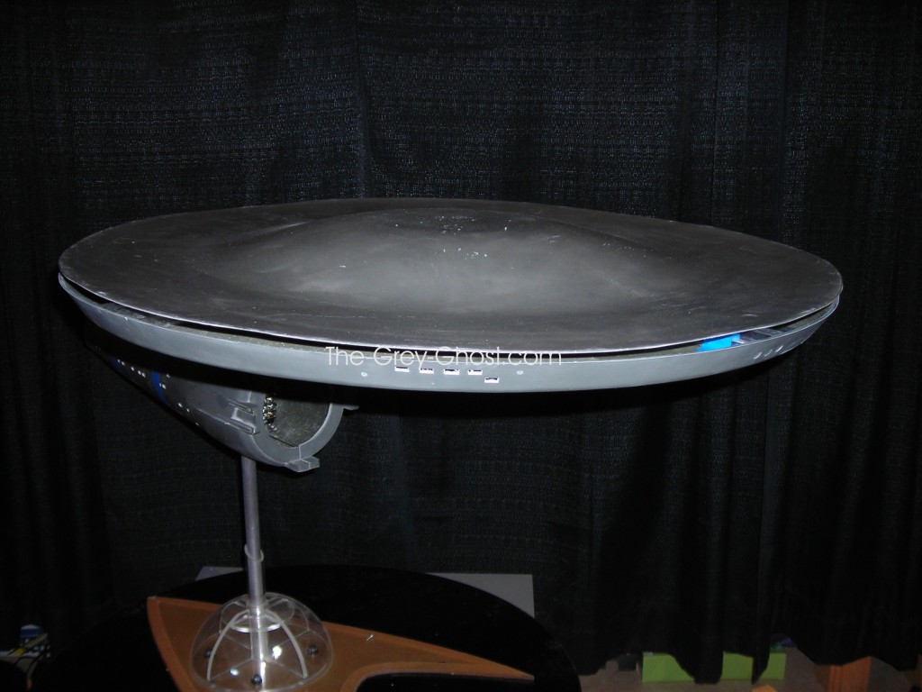
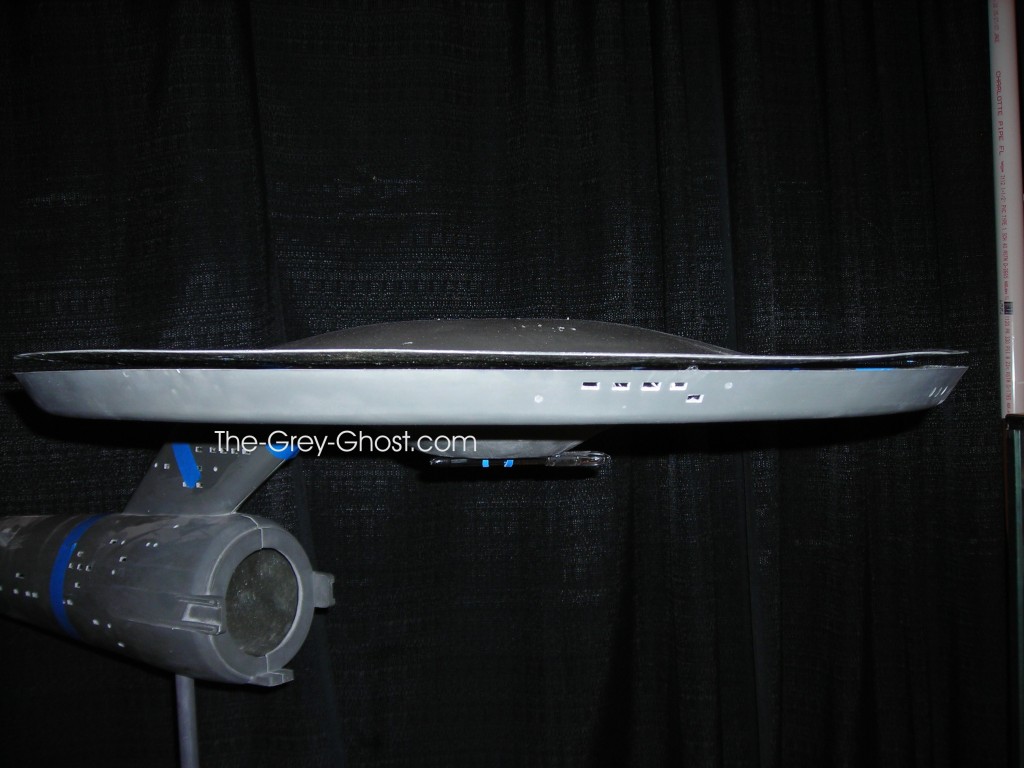
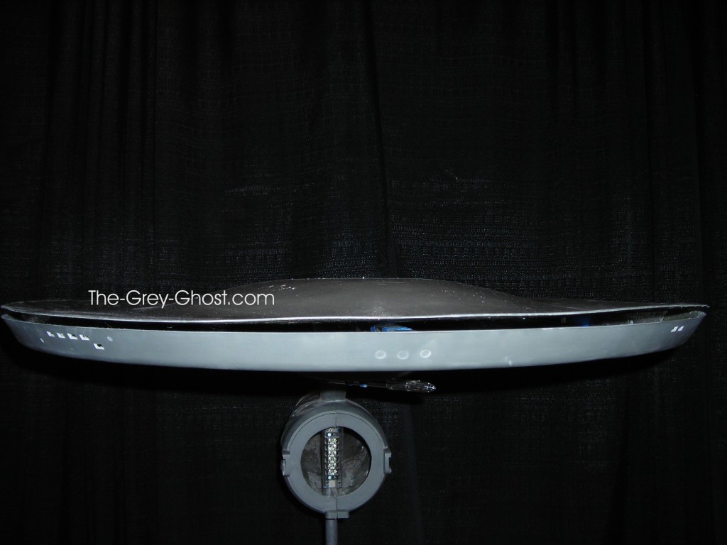
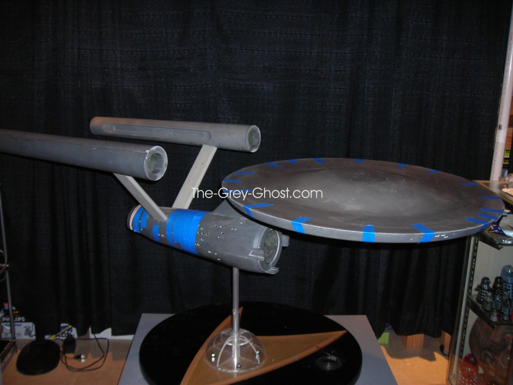
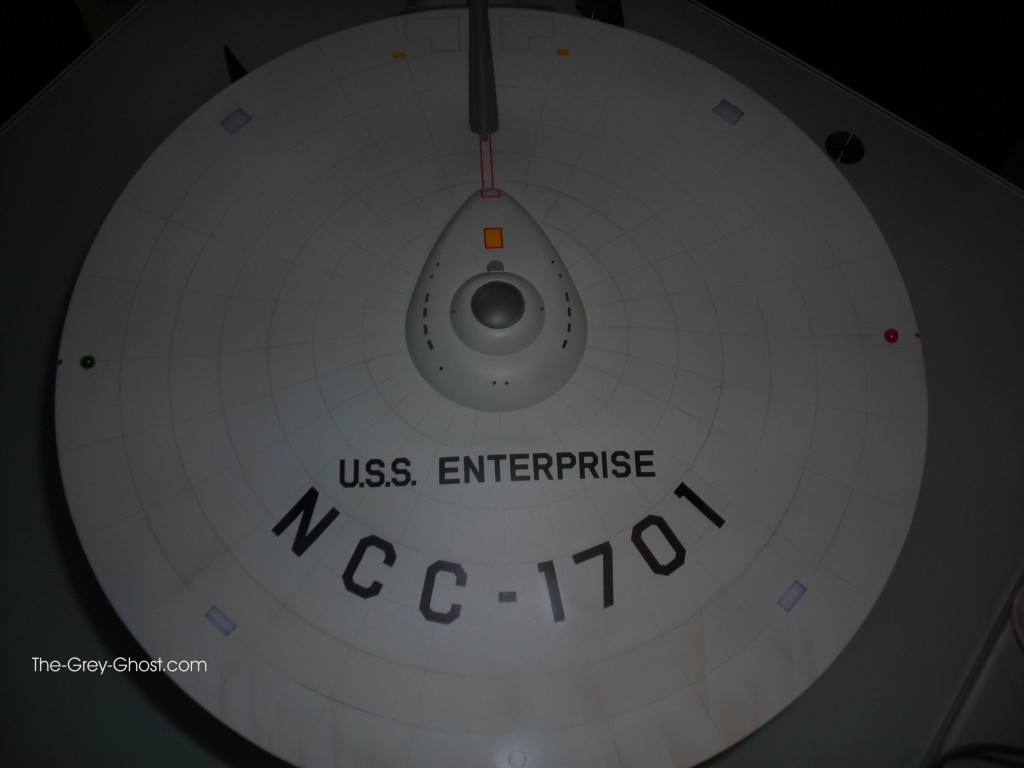
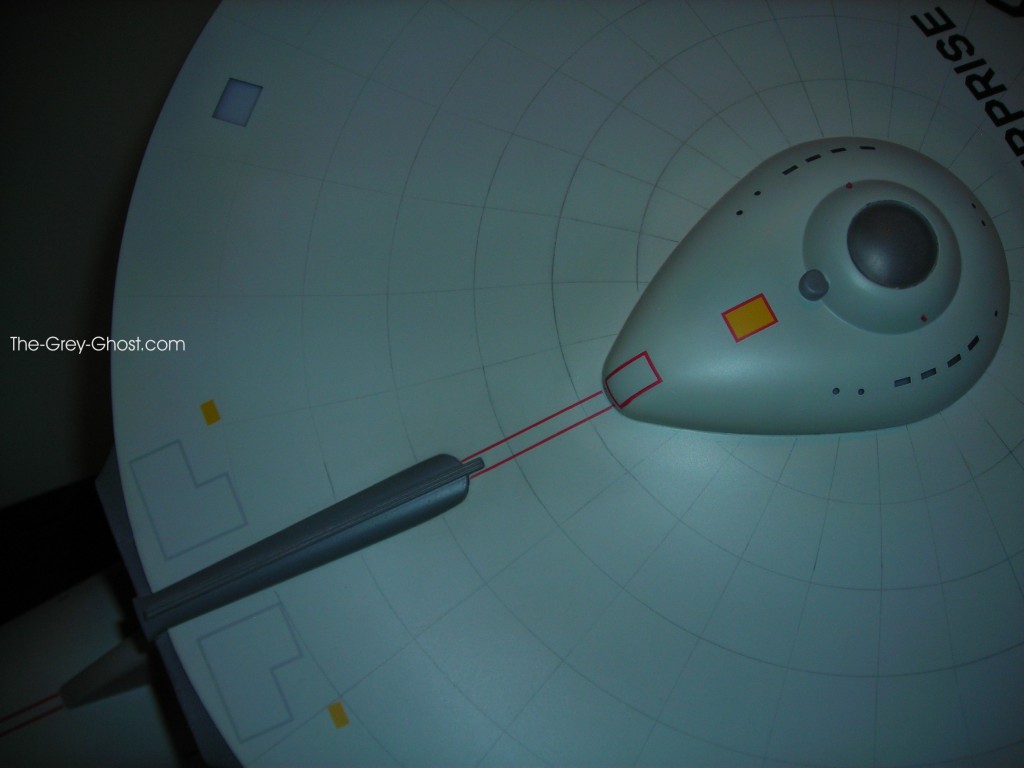
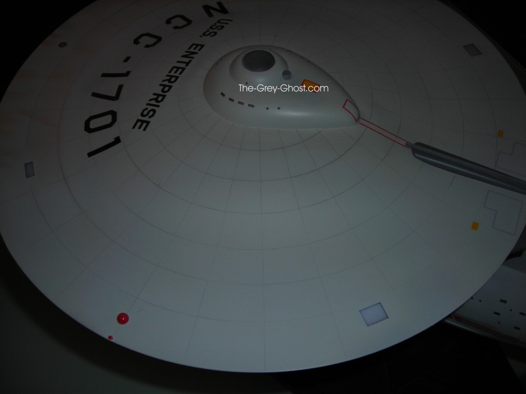
Custom Replicas 66″ TOS E or why work hard when you don’t have to.

After the primer stage it’s time for some assembly.

I mentioned the instructions that came with this kit is only good for a very loose guideline for building this model. (This is something for those of you out there that think you have to follow the instructions absolutely). The people that create these kits are not infallible, they can’t think of everything.

Contrary to some people’s opinions they are only human like all of the rest of us.
Here is one of the issues I found that if I followed the instructions. This task would be considerably more difficult. This pic is from Sean Sides build to illustrate my point.

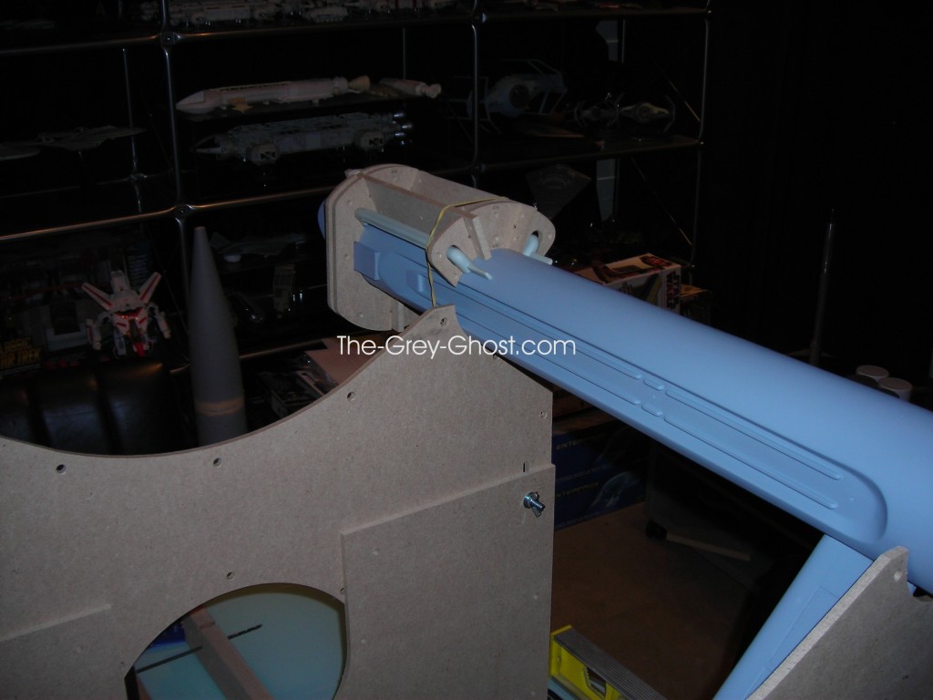
Note the ends of the warp nacelles, what they are being supported on. This is what your supposed to do to align and level the engines. Along with taping across the pylons to the correct angle. Now the problems with this method are numerous, but in the hands of a pro like Sean he makes these things look very easy.

What s wrong with this method?

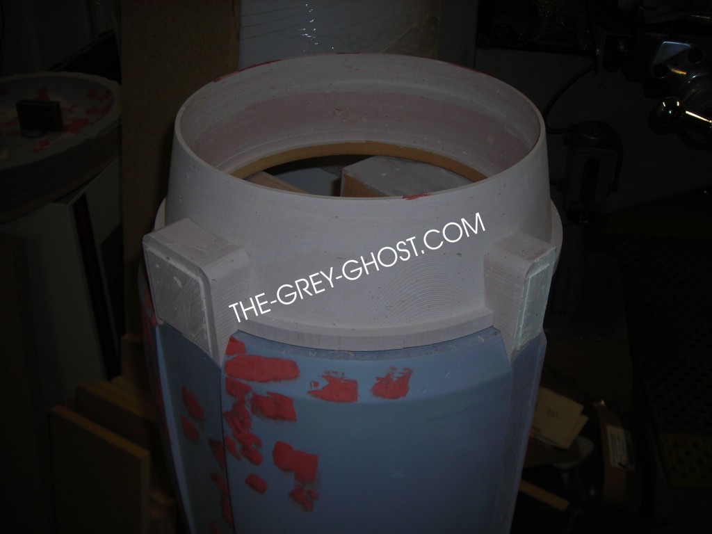
Your expected to support and align the engine on the ring below the endcap(pic above). It isn’t attached to the engine, according to the instructions that’s what you’re supposed to do first. I didn’t like this method because if this piece is not centered on the nacelle, the whole nacelle will be out of alignment.

If your going to align the engine you want to use the parts that are solid and hopefully straight. Where is the best place to align the nacelle?

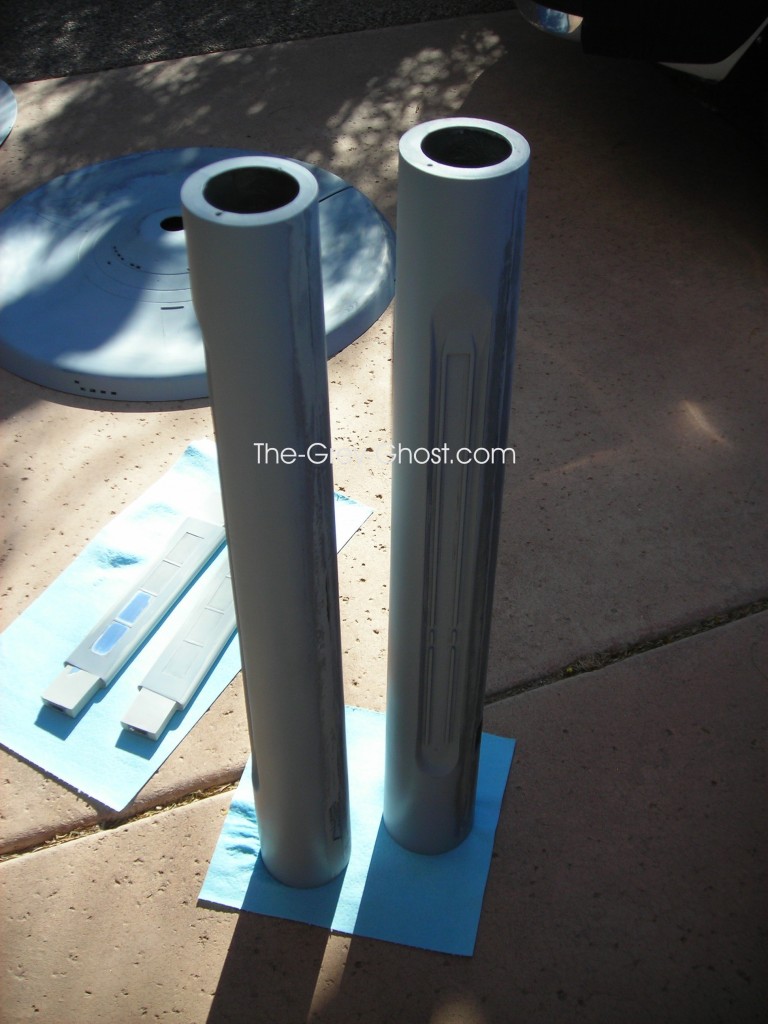
From the long tube that makes up the nacelle, I don’t have to glue anything on to support the whole thing. But I do need to do something to support the nacelles in front of the pylons, for they can move there just as easily as they can on the other end. So I need a method to keep them in line.

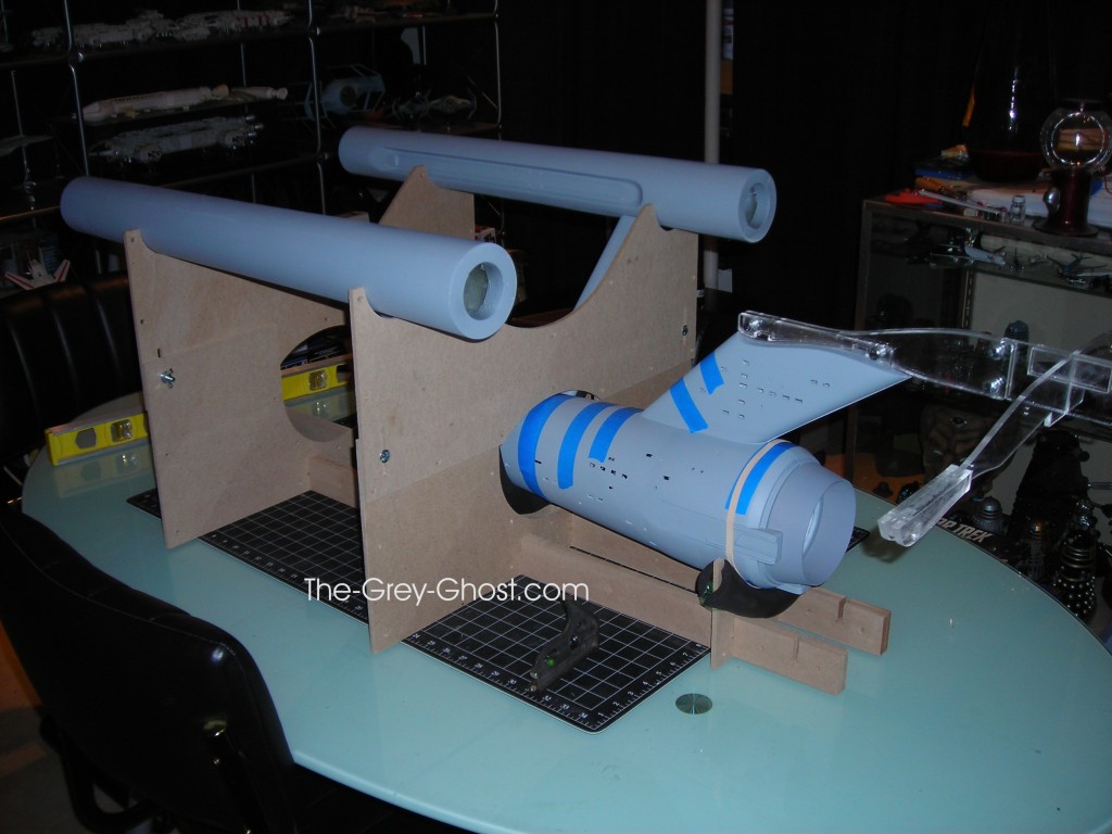
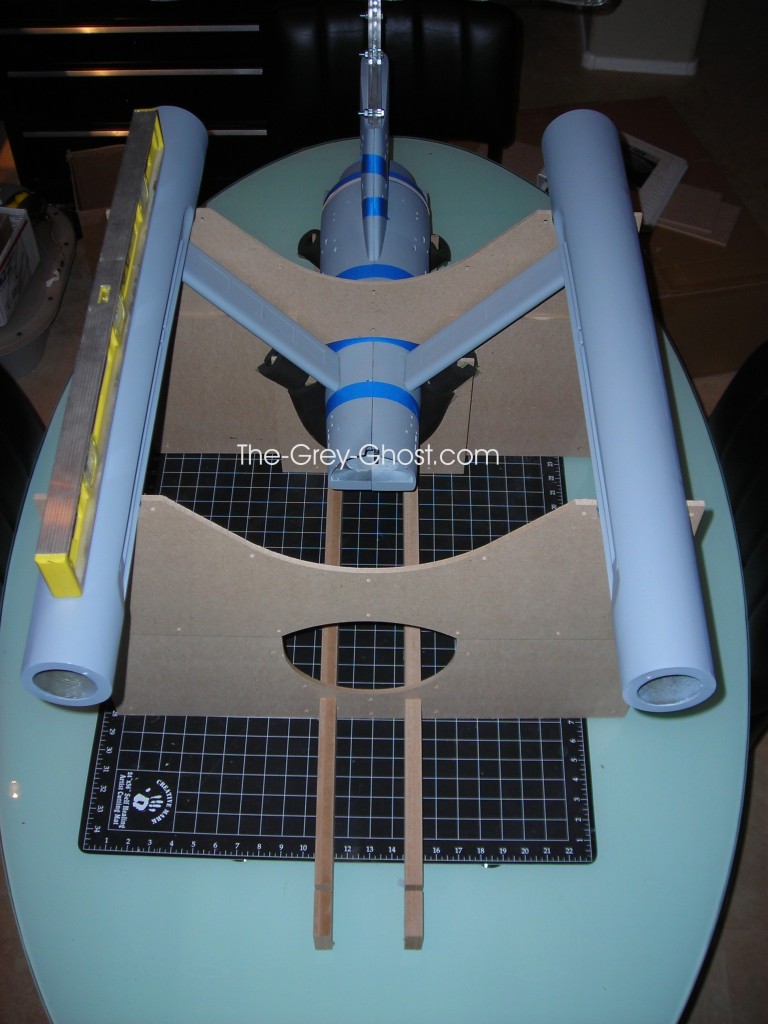
Here is what I came up with.

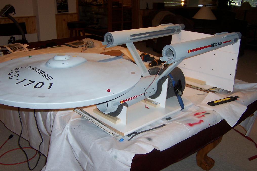
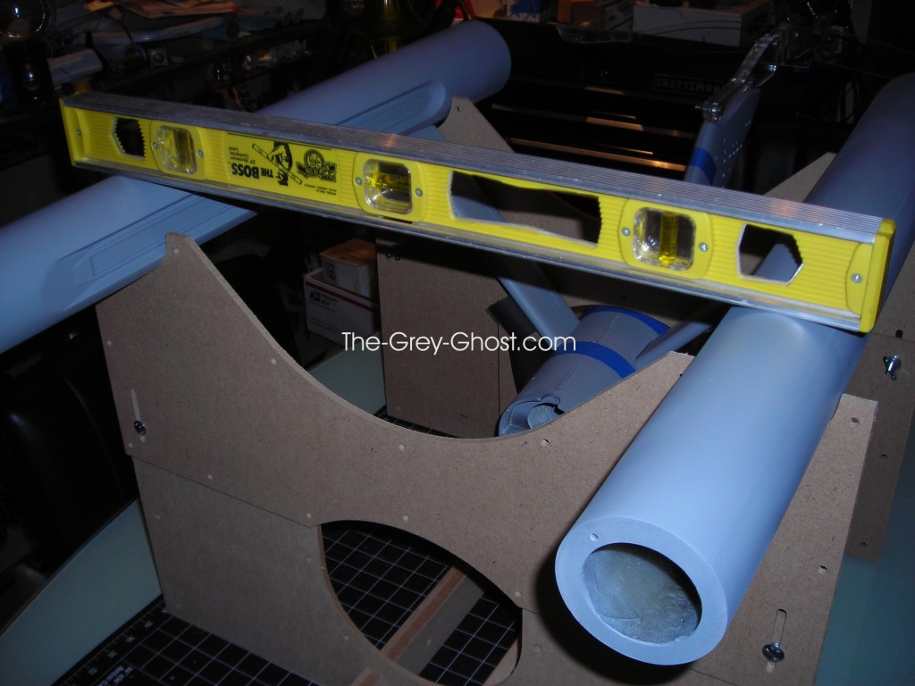
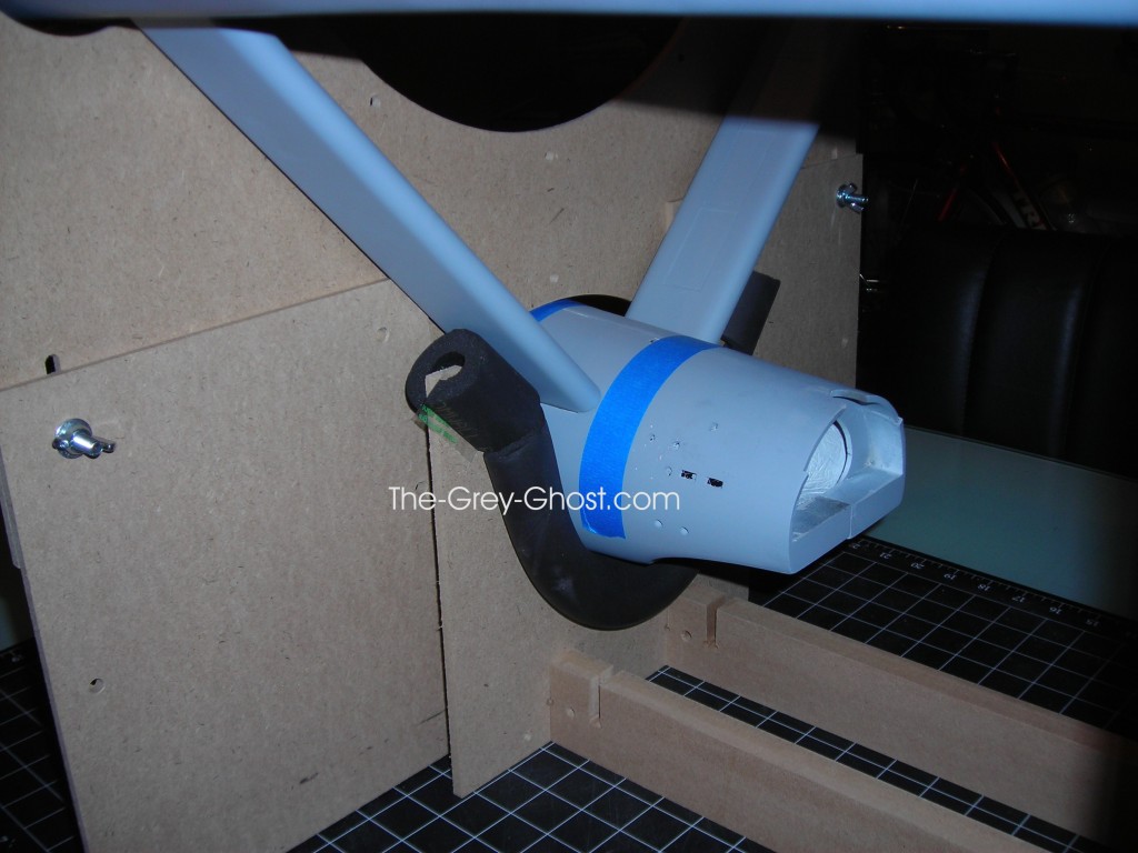
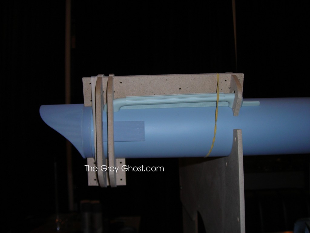
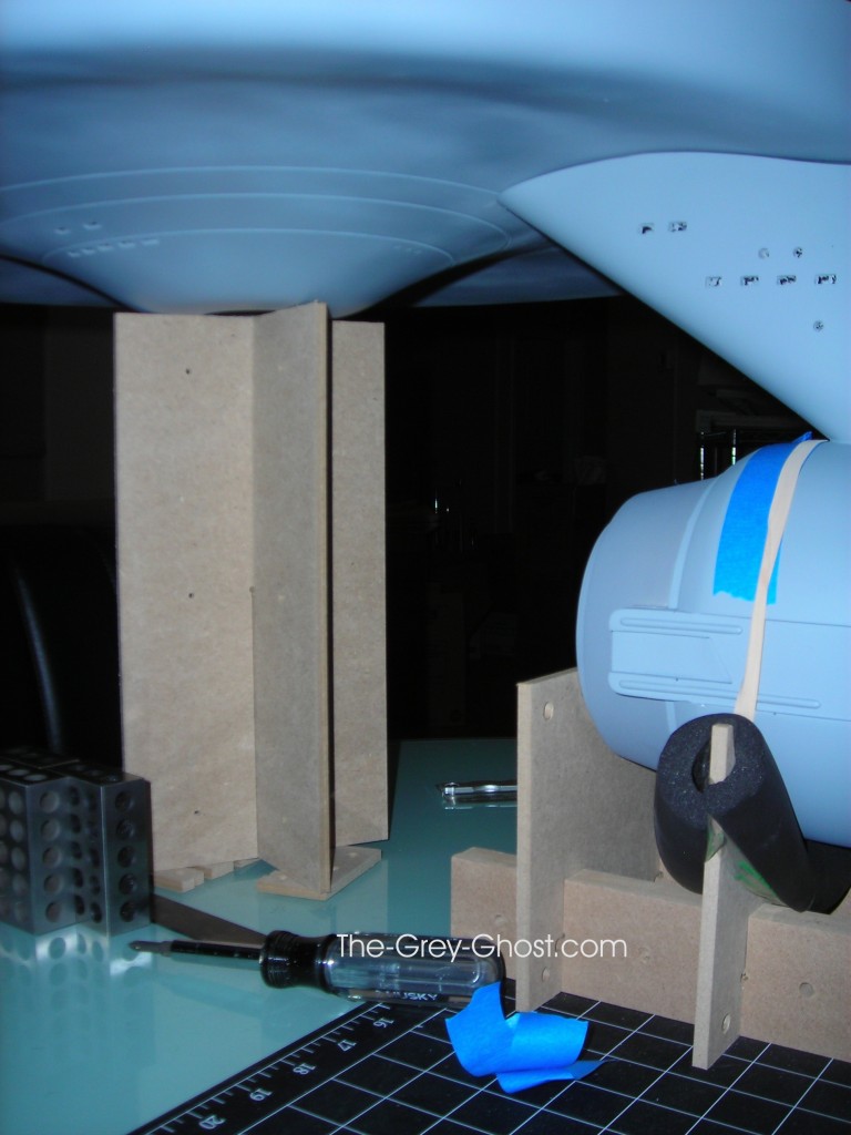
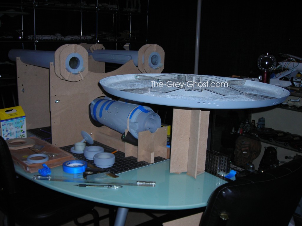
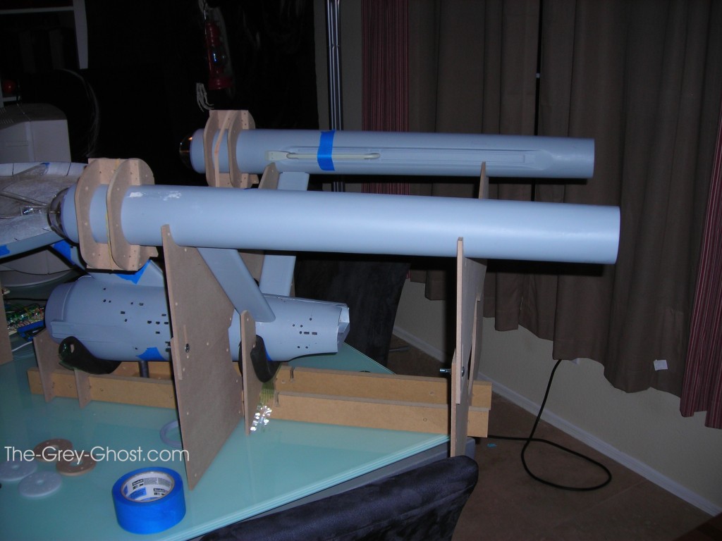
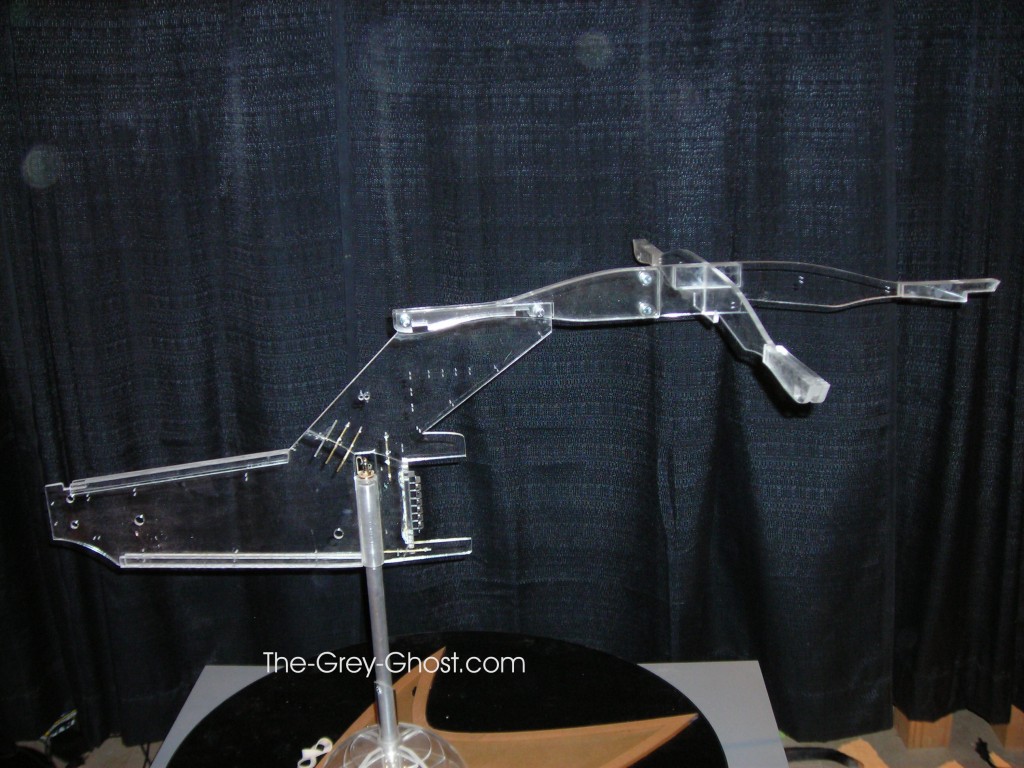
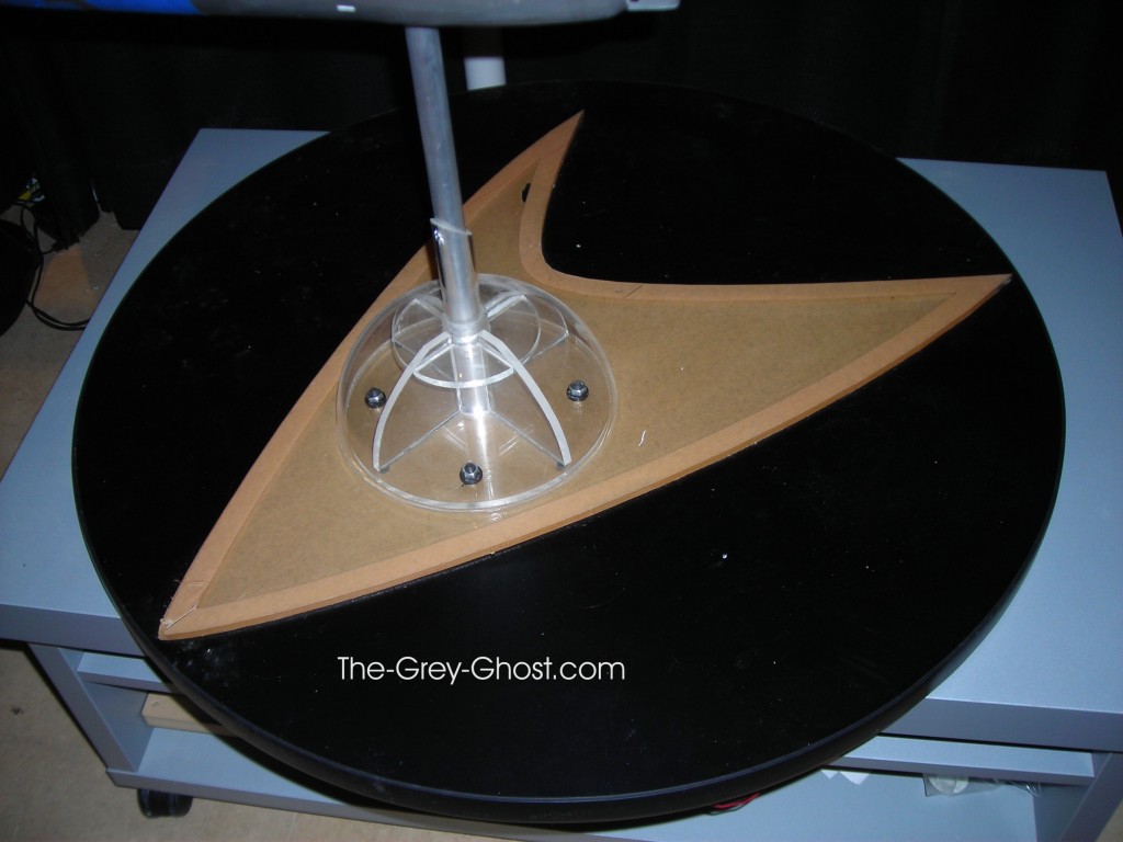
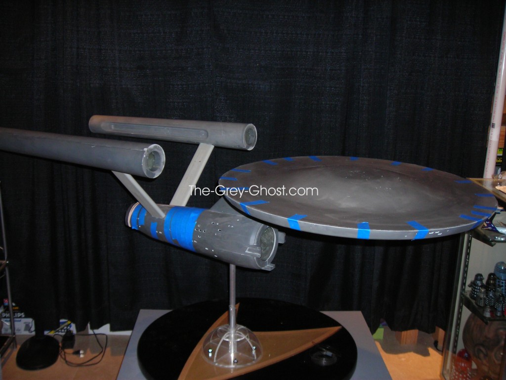
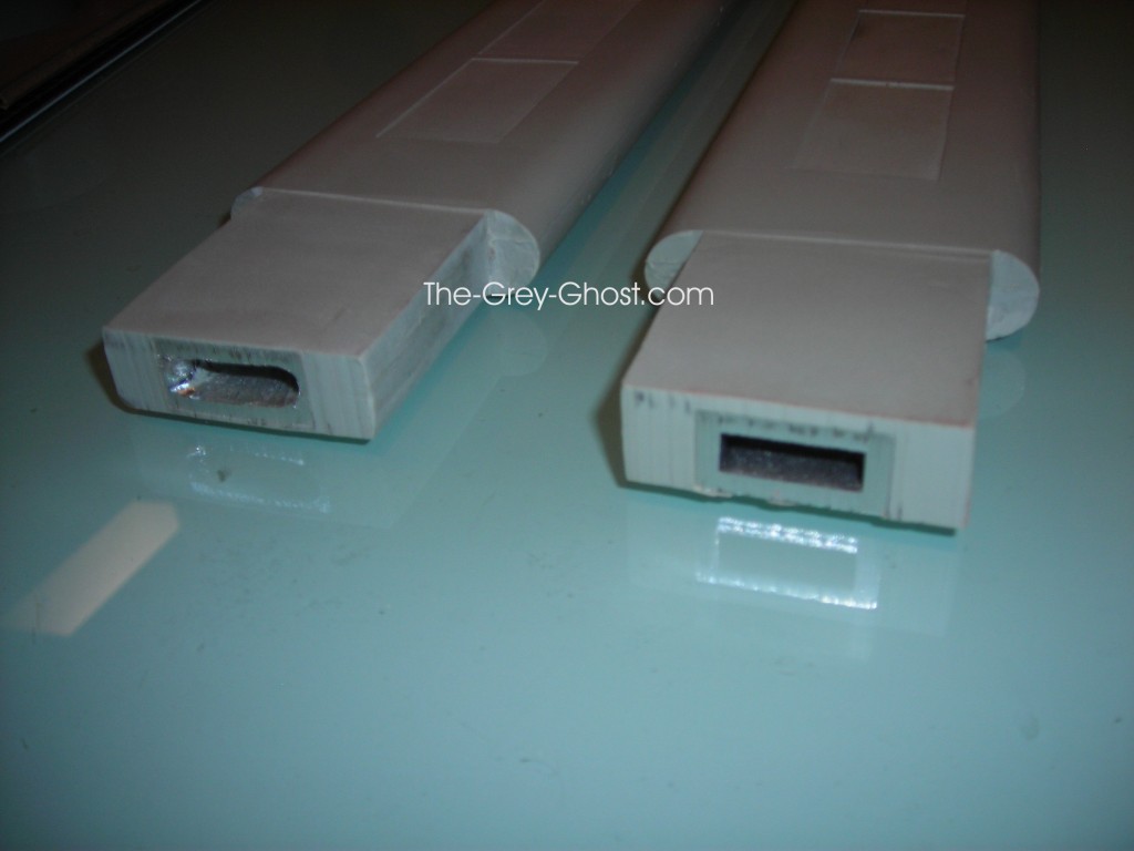
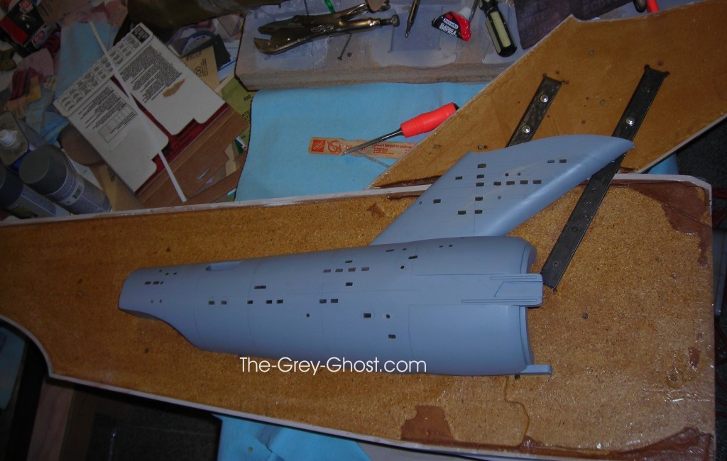
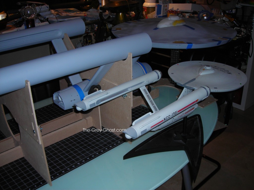
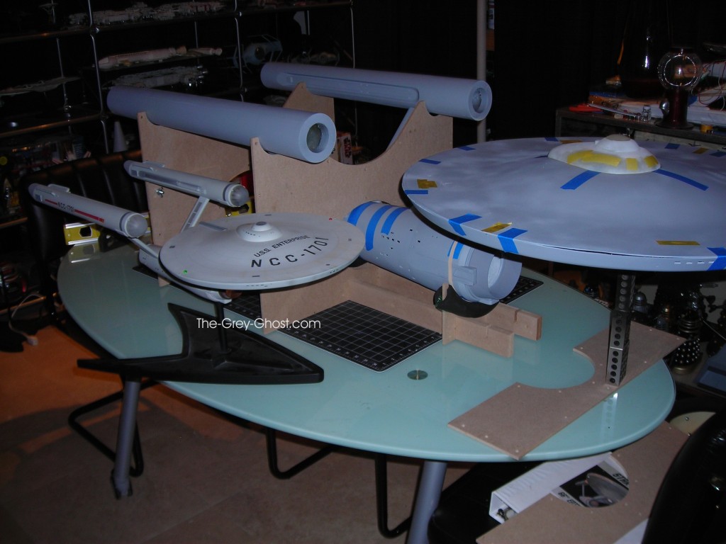
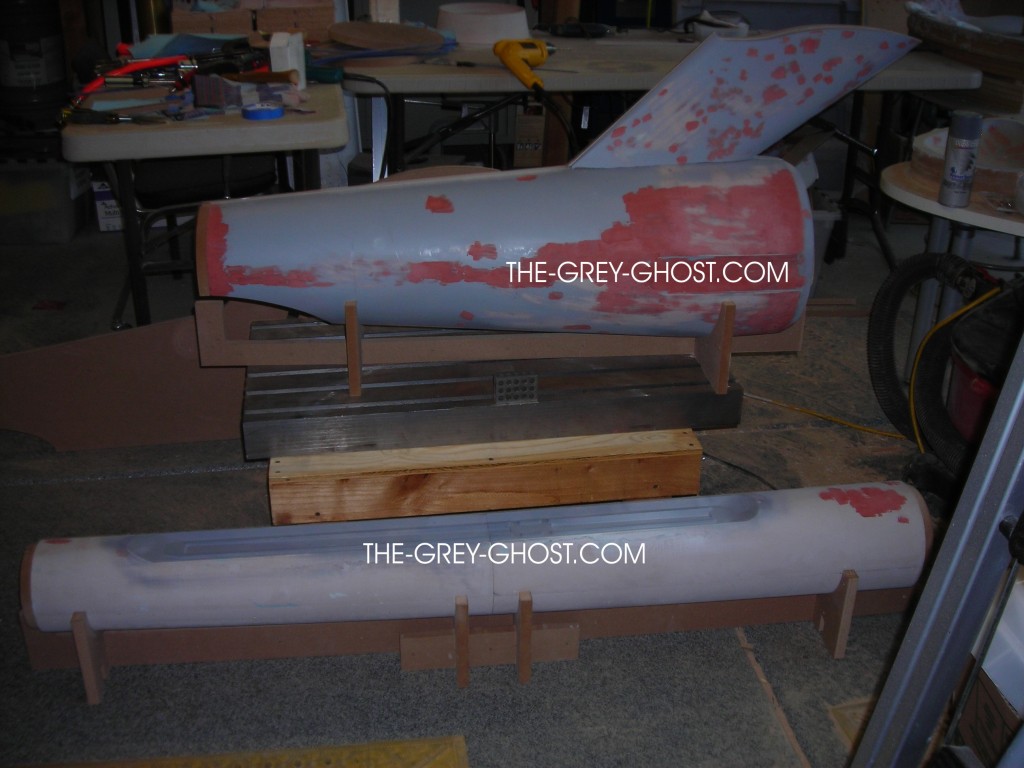
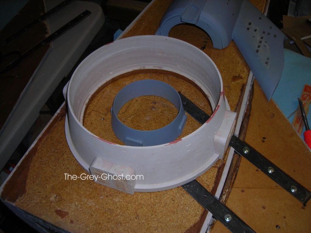
This is called a jig, it’s used to align parts so you can put them where you want them. These sort of things are common in industry, so why not with models. The rails below the model have slots to accommodate the jig apparatus. There are six slots for this model, the first is a stop, the second supports the 2nd hull, the third supports the engines and aligns the pylons, the fourth supports the hull under the pylons, the fifth does the same job as the 3rd, and the last supports the nacelles.

The parts that support the nacelles can be adjusted, to level the nacelles.

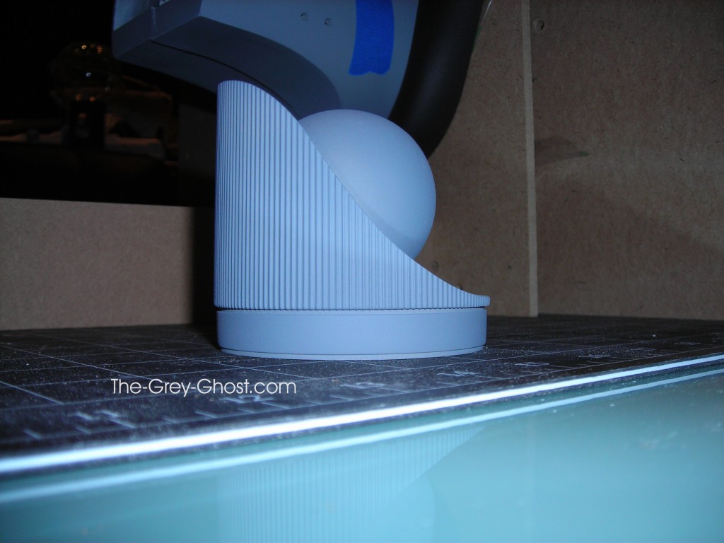
Here is the part that supports the nacelles, and aligns the pylons.

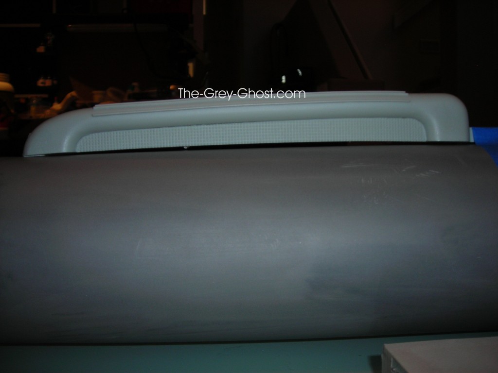
Here is a way not to level the nacelles. Since they are tapered it would be pointless to do this. because the results would not be desirable. You will see there is one more slot position on the end of the rails. These are the positions indicated by Custom Replicas to support the nacelles(which are redundant, now). Now that I have a jig for the hardest part of the model to align, is there anywhere else on this model that could use a jig.

The answer is yes.

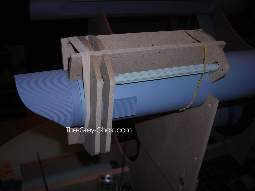
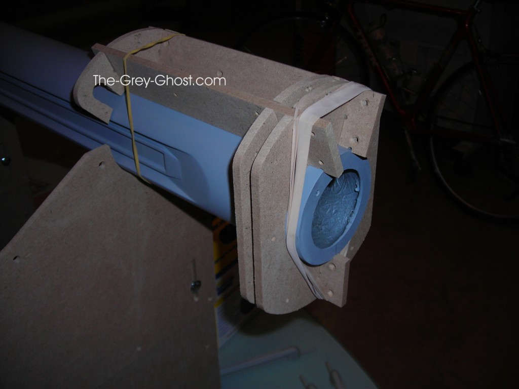
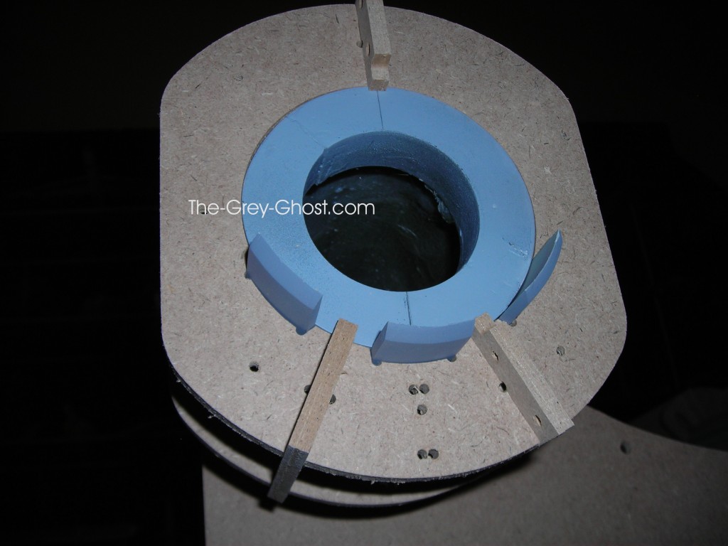
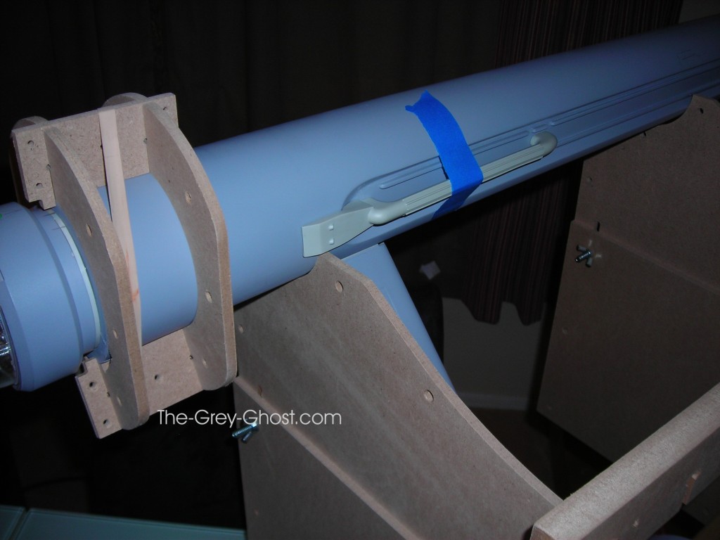
This jig is used to align the parts at the end of the nacelle, it works for both sides.

It provides a stop so the parts are placed into position.

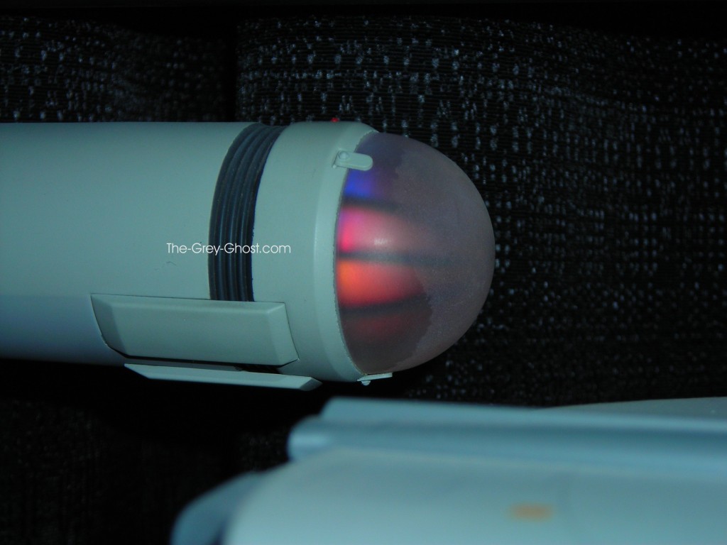
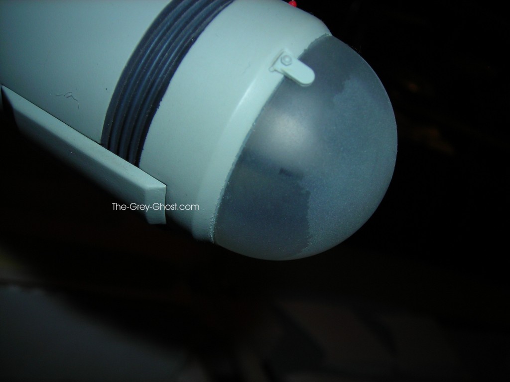
It does something else, it aligns the troubled endcap.
Lucky the ends of the nacelles are more or less the same size. That isn’t the case with the forward parts of the nacelles.

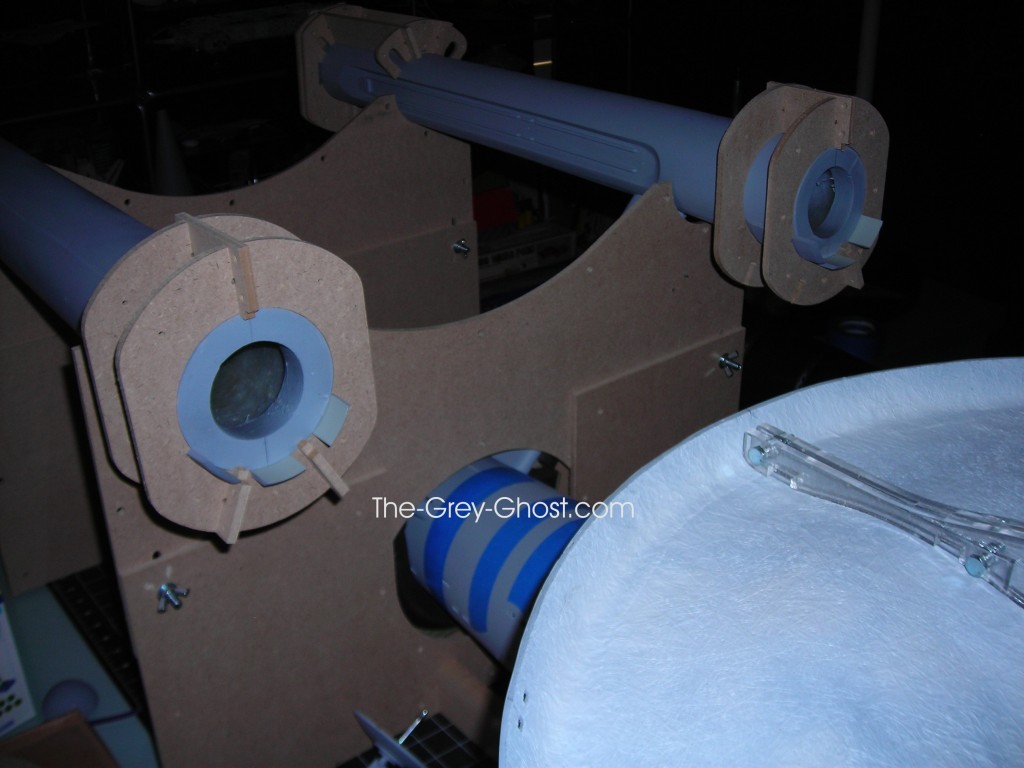
The fronts of the nacelles were different sizes, so I couldn’t make one jig for both sides. The funny thing was the manual stated, “The correct diameter of the front of the nacelle tube is 3.685″.” When I measured the parts, I didn’t get that number on either of the nacelles. After all it is a garage kit, to expect that kind of precision is ignorant or delusional.

These jigs were only for the dome shields. I’ll go into how I aligned the bussard mounts later(That’s just as easy).

I realized I needed something to support the saucer, it’s shimmed to get it to the right height.

After some time I made changes to the jig.

I shortened the rails and…

allotted for the flux chiller, there is a stabilization rail to keep the nacelle jigs in line.

If anybody want’s one of these jigs for this model, contact me at “commandermax@the-grey-ghost.com”. It makes building this kit a lot easier.

The next thing is the lighting, it has been taking me forever. But the results are amazing.


66" TOS E, Models and Props

Custom Replica’s 66″ E part two, the model.

The more I was looking over this kit, the less interesting it became. This model is more or less the same as the 350 scale Master Replicas Enterprise. I already have one of those, so why build something that’s just a bigger copy. When I can do so much more with it.

More on that in future posts.

Before I can get to the neat stuff there is a lot to do.

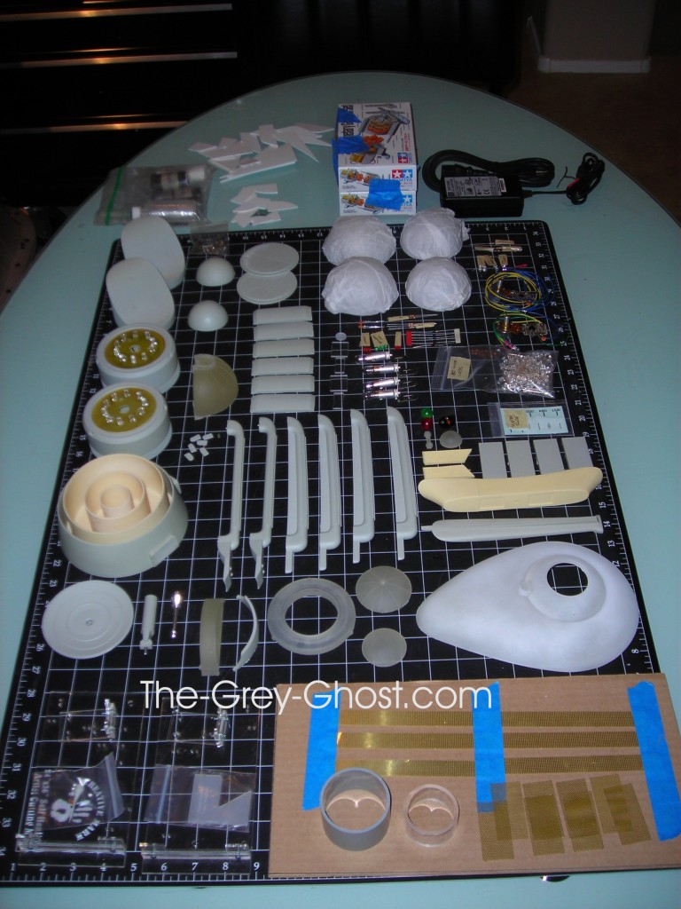
Here is a table of parts, less all of the big pieces. Some stuff is useful some is not.

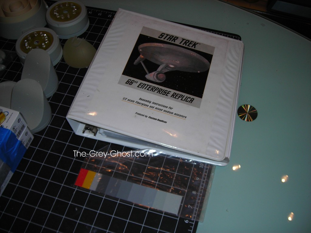
It came with a cd with the instructions and pics. So I made my own manual. It did come with paint swatches, which is very helpful for somebody like me who can’t mix paints to save my life. So I would take the swatches to an auto-body supplier and have them do it. Before you can say I can use them on the Big E, well not exactly. When you scale stuff up(or down) the color has to change. Unless somebody knows if these were taken from original paint chips?

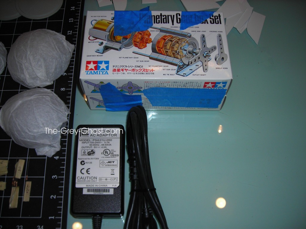
You see on the top of the image the planetary gear box set. These are for the spinners, I consider them junk, they are real noisy, the gears are styrene and the shafts are to unstable for a kit like this. I’ll go more into this when I show how I redid the spinners.

Here is the armature.

And the base.

All the big parts together.

Here is some details, and a few issues.

For some reason some bits don’t want to leave the mold. Most likely mold release issues. Just another spot to fill and sand.

This sort of thing can happen with a thin long part, give it a few minutes with a heat gun(on low) and problem sorted out. 

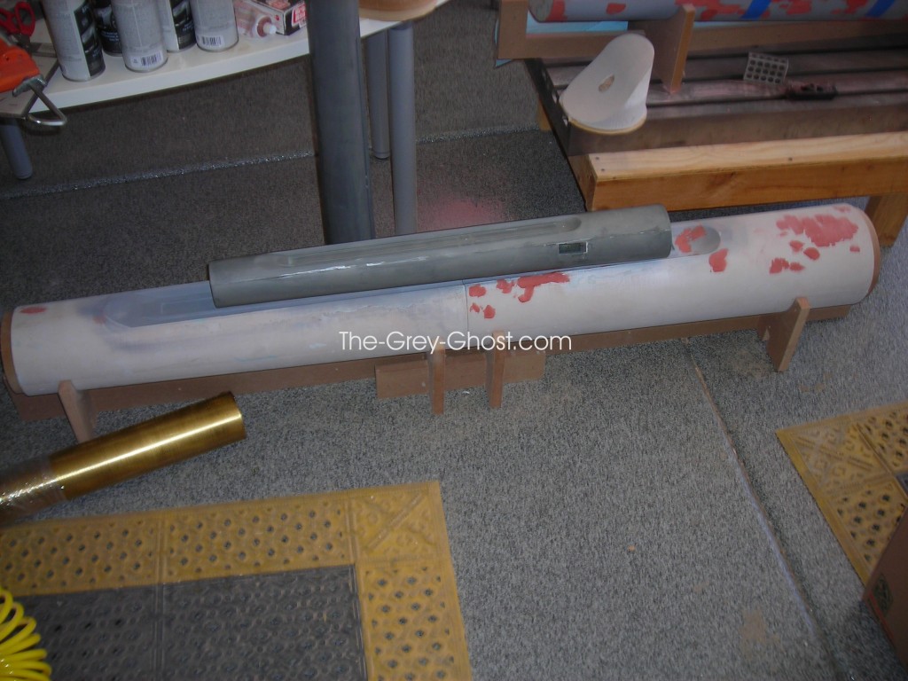
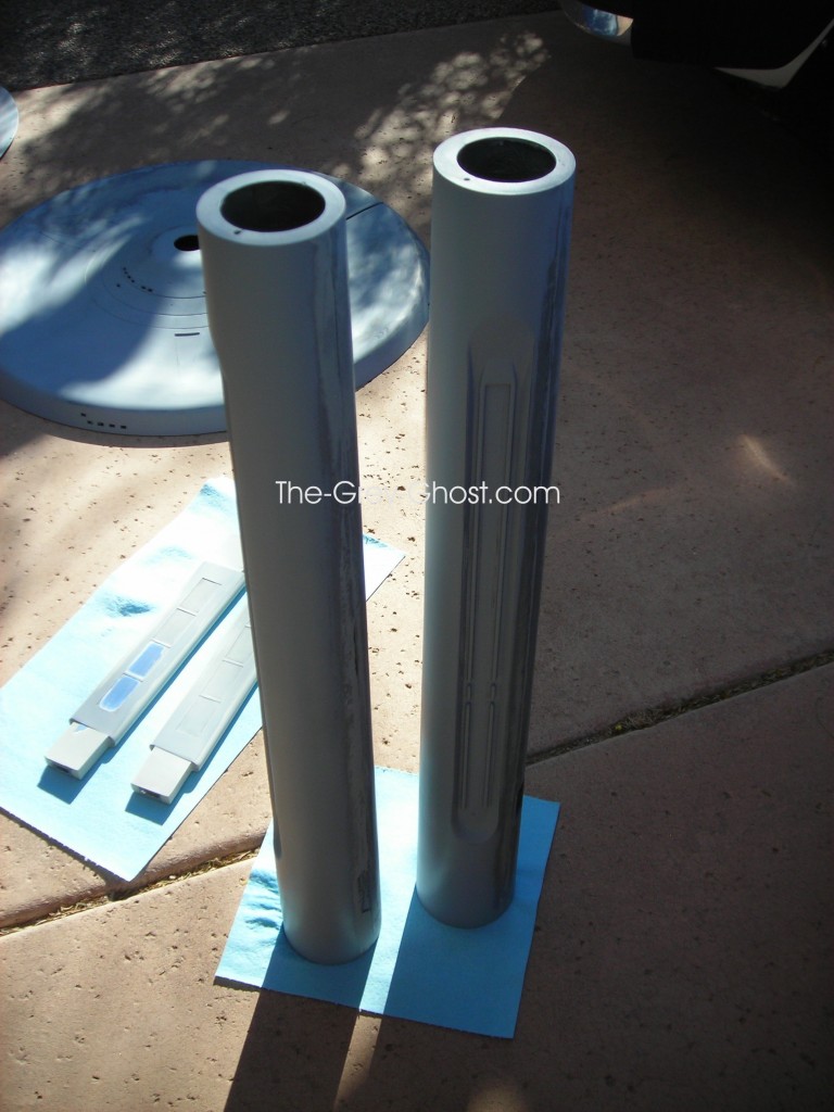
Here is the pylons, they have an aluminum tube cast in to them. For electrical and support.

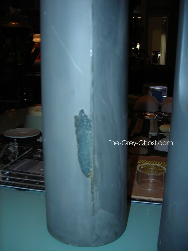
But they were not placed with care, see the bits of the tube shining through. Really it isn’t all that important they are going to be covered up with grill work.

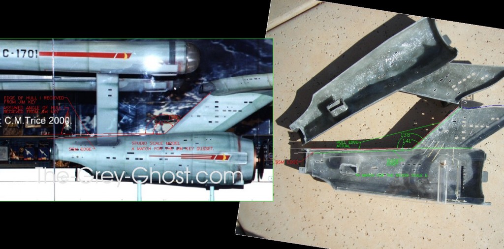
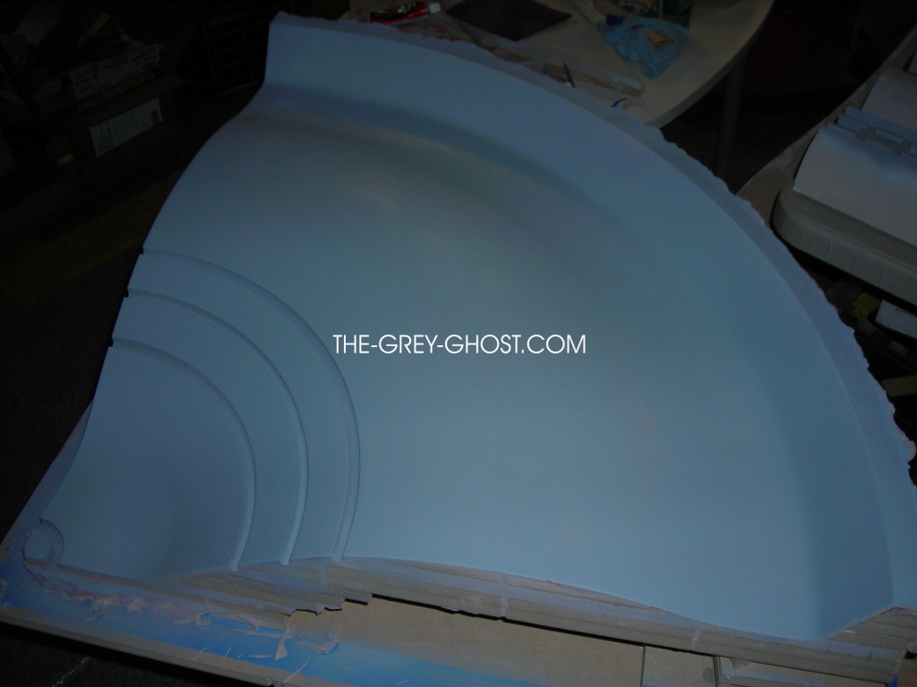
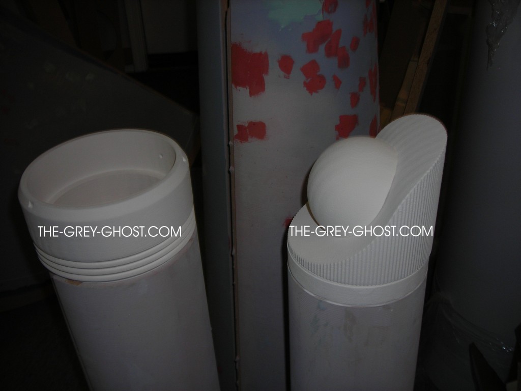
Here is some parts comparisons, between the 66″ and studio scale(some parts are primered).

Saucers

Nacelles

2nd Hull’s

Deflector Cone.

In the world of models primer can revel all.

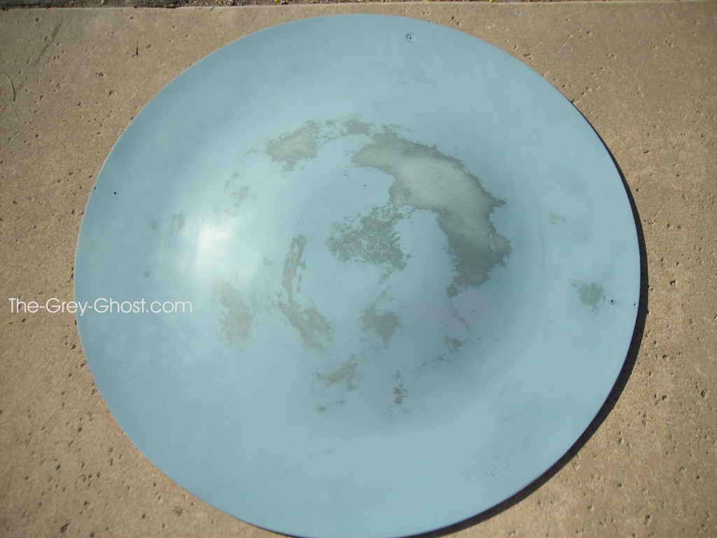
No wonder the saucer gets out of shape, it’s very thin. The swirl/cloudy areas is light coming through.

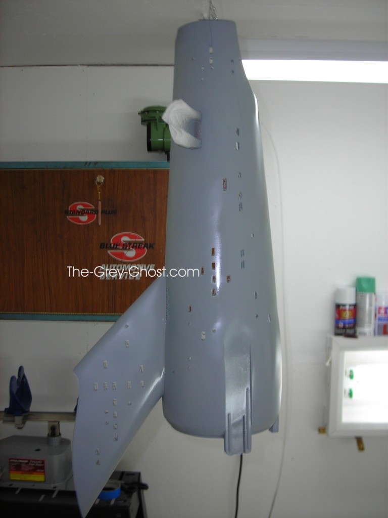
2nd hull freshly primered.


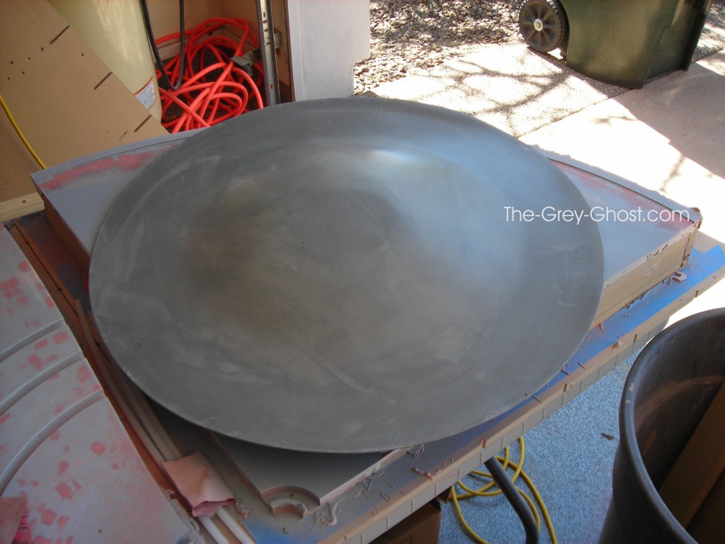
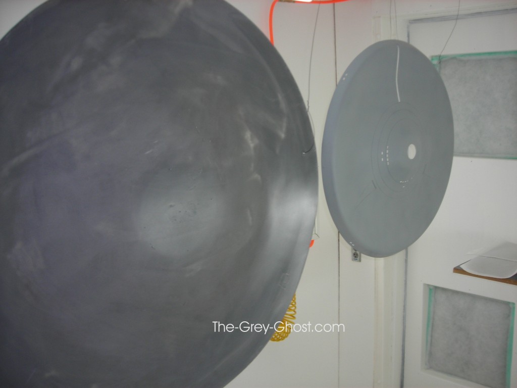
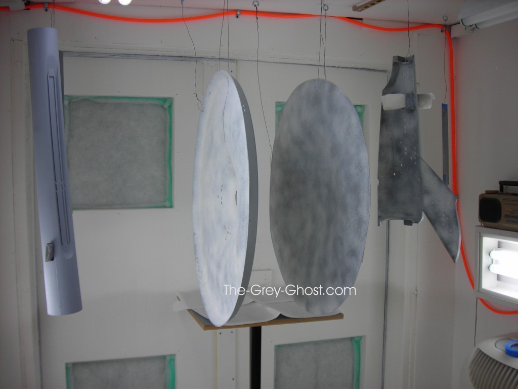
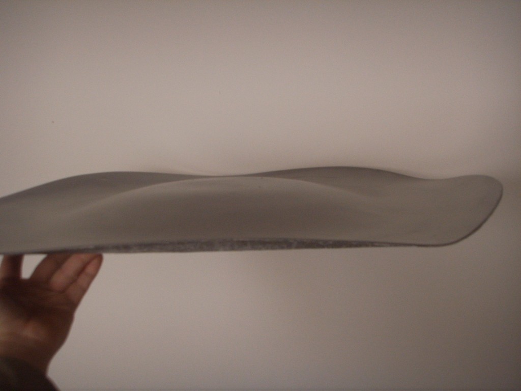
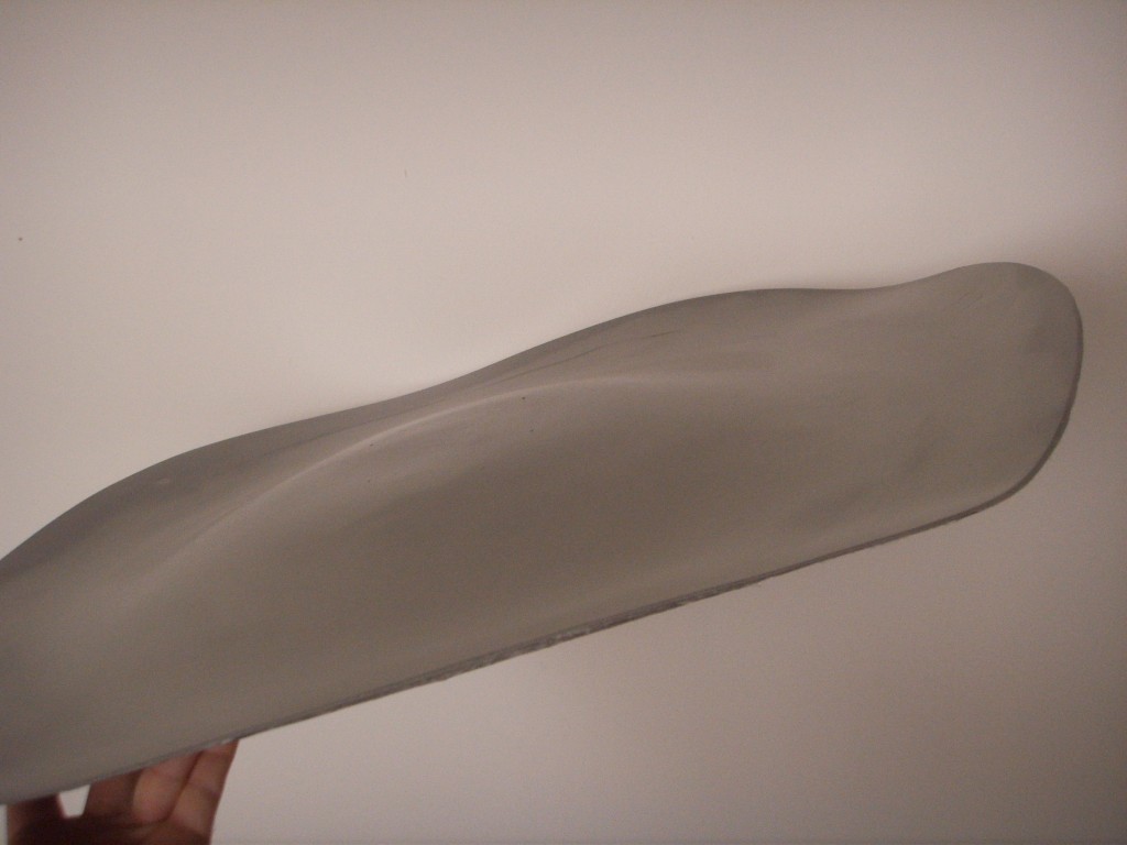
These are hanging to dry, note the upper saucer(far right) it reminds me of a warped record.

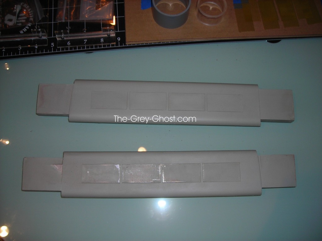
I dusted the backs of these parts with white. After the windows are done I’ll do it again.

I have wetsanded the parts, it shows what areas needs attention.

Upper saucer(it did flatten out a bit in the sun).

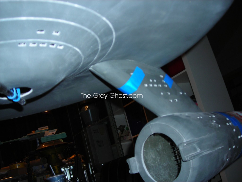
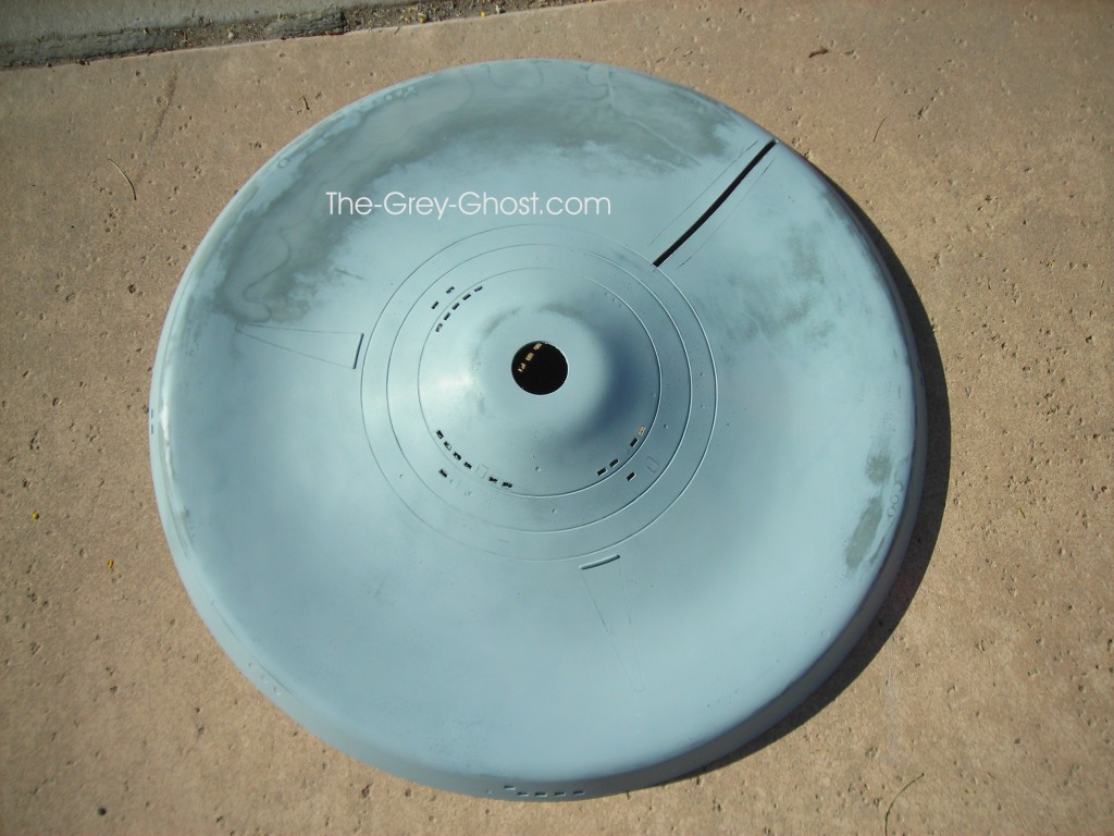
Now I have to say something about the lower saucer. If you look just to the side and below of “The” you’ll see a wavy line in the saucer. That works it’s way around about 1/4 of the saucer. It causes me great concern, it’s a raised part of the surface. I thought I could sand it out, but I realized it’s under the saucer. Why bother if nobody is going to see it(I hope).

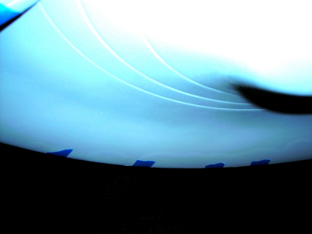
Here is the same problem area(the wavy line just above the blue tape). I’m pointing this out for it could be an indication of another problem. I showed the problem area to a friend, he said poke it with an x-acto. So I did, lucky for me the area wasn’t hollow. If it was it would mean major rework of the saucer. Voids in the fiberglass indicate a poor layup or there is an issue with the resin and the fiberglass is separating. Since I had other issues with fiberglass on this kit I was understandably concerned.

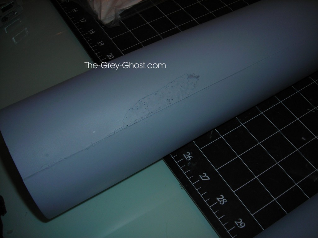
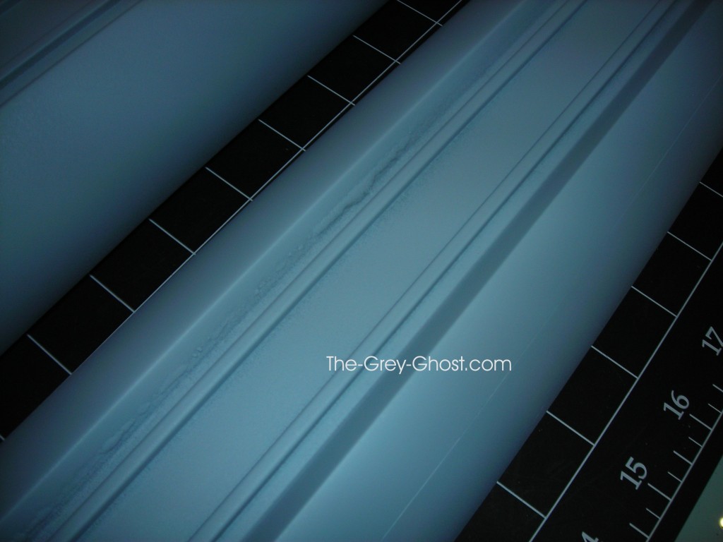
Here is a close up of the pylons. Remember the areas there the aluminum was showing through. When I primered it the resin was so thin it started to curl. Again these areas are going to be covered up by grills, not a big deal.

Here is some of the errors I found after primering.

Definitely a few bubbles here and there on this kit.

This is the spot from earlier, primering made it look worse.

This kit is just like any other garage kit, it’s going to need it’s fair share of work to get it right. I’ve seen worse and I’ve seen better.

To be continued…


66" TOS E, Models and Props

The Custom Replicas 66″ Enterprise or be careful of what you wish for…

You might get it, and find out it’s not as wonderful as first perceived.

When I saw Sean Sides build of this kit I really wanted one. He did one heck of a job.

He has much more on his site it’s well worth the visit-

Square Models

This model was Produced by Custom Replicas, I got one in 2007.

There were damaged parts from shipping, those were taken care of by Custom Replicas. But there is always a period where you can only see with rose colored glasses. When they came off I found a very big problem with this kit.

The supplied armature didn’t match the hull. At first I was confused maybe it’s supposed to be that way. I did try to ask Custom Replicas about it at the time, but I never received a reply back. I didn’t have time to peruse the issue because I moving at the time. After I was settled I took it up again, but I got a very cold reception. I was told there was a 90 day warranty period and I would have pay $100 to get a new part. Without this part the $3100 I spent on the model would be wasted. After a few email exchanges, I figured it would better to pay for the parts. These guys were really making things difficult. I asked a friend if I could fix it, he told me no. The fiberglass didn’t have enough layers to keep the part stable. So I reluctantly paid for it and got the replacement second hull. That one fit the armature.

At the time I was so frustrated with this experience, I put the model back in it’s boxes and left it to rot on a shelf. Maybe one day I would build it, after some time had passed and my temper cooled(I have this issue with a number of models in my collection, buying garage kits can be a very frustrating experience).

Until a friend showed me these-

Uh oh, that’s not good. It’s the upper saucer from the same kit I have.

So I went and checked the condition of mine(I haven’t looked at it in years).

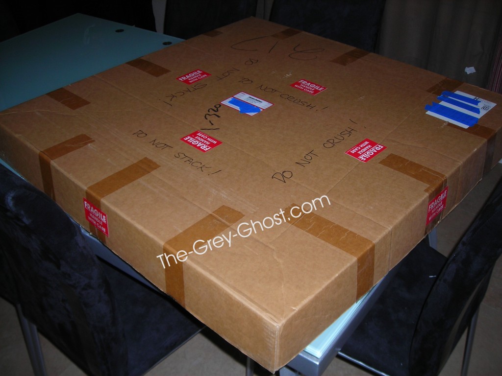
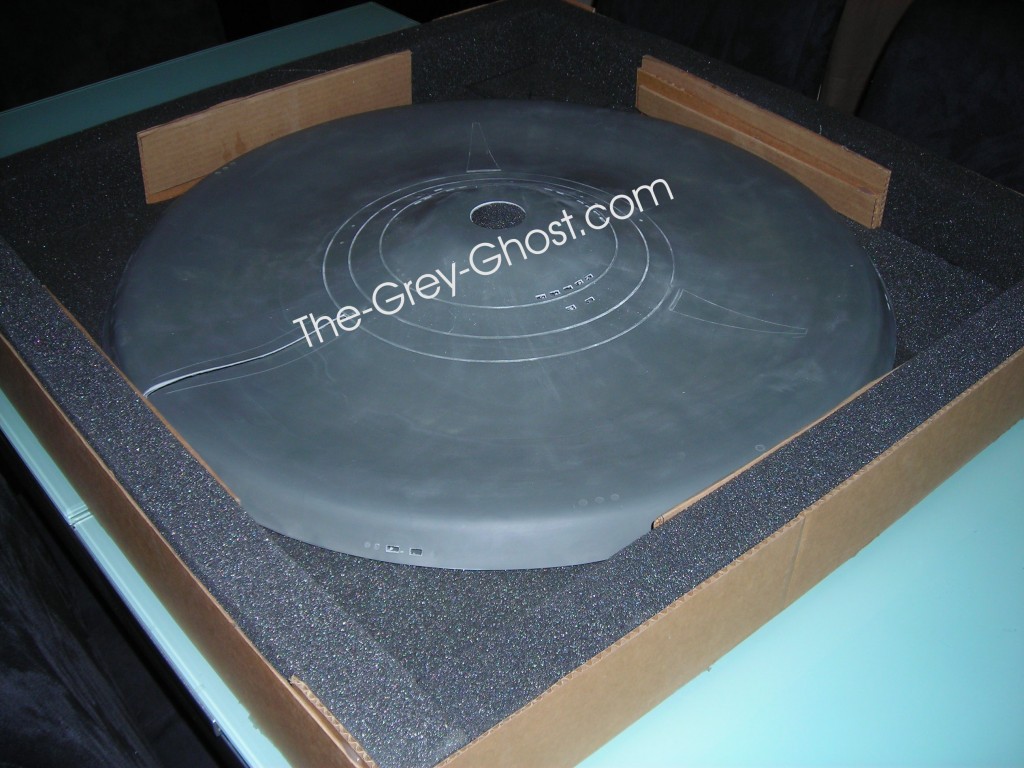
It came in a very big box.

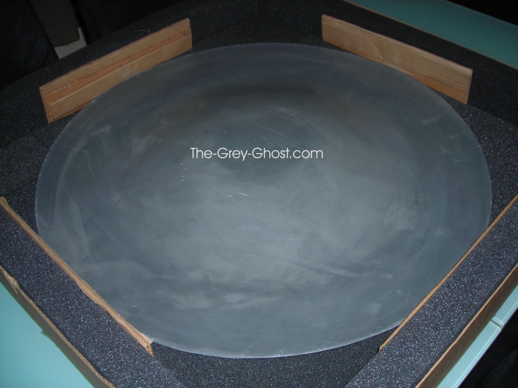
It was stored in the original box. I took it out and checked it’s fit(I wish more companies packed their products with such care). This is the upper saucer.

But first I have to do some dry-fitting.

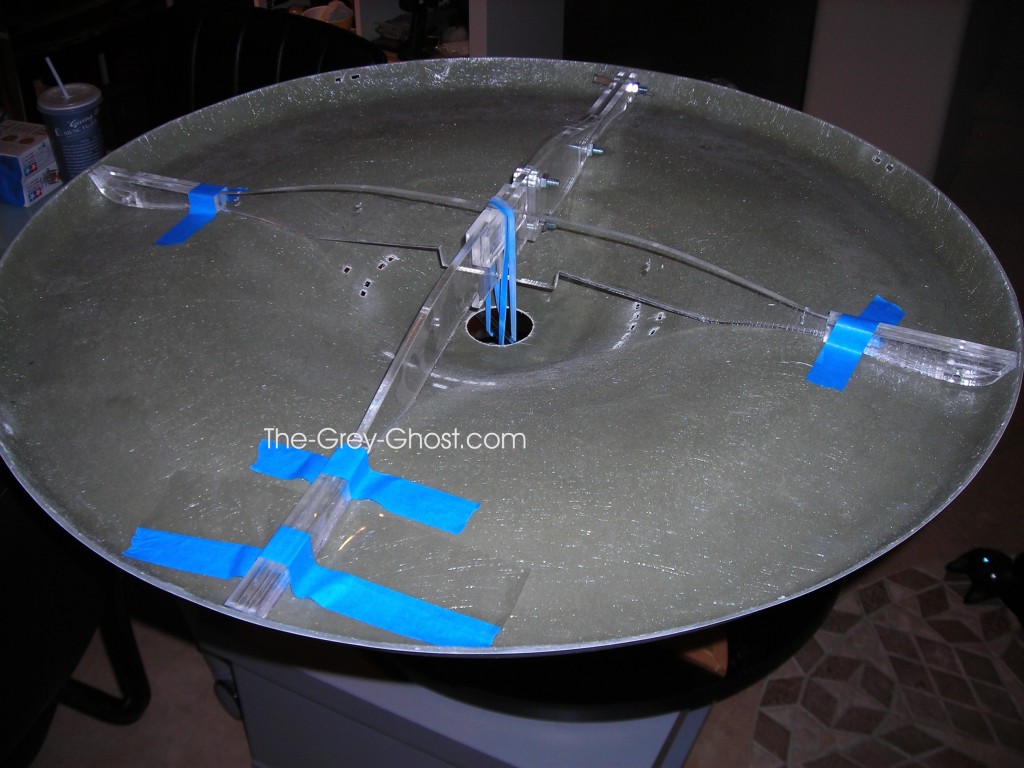
I needed to secure the armature in the saucer securely(only temporarily), So I used a pen and a rubberband.

I had to make sure it’s well seated to the second hull.

Then I put the upper saucer on and…

Yea, that’s kind of wonky. But…

That doesn’t make me feel comfortable.

Yep, the shape is changing, eventually it will look like my friend’s saucer if left alone.

With a lot of tape it can be held down, so it’s going to be ok. But I have to build the model so this issue doesn’t get worse.

You ask why is this happening? Heat? Cold? Apollo showed up? Kirk pushed her one step to far?
Nope it’s physics, the material it’s made out of is polyester. A relatively inexpensive type of fiberglass(there are a lot of different types). But the fundamental problem is, the saucer was to thin to resist the tendency of the material to do what it wants. Which it did. If the upper saucer was made thicker it wouldn’t have been as big an issue. Gluing the saucer together will solve the problem. This doesn’t happen with all types of fiberglass. It was just a poor choice for this part.

I strongly urge those of you with this kit on the shelf-

TAKE IT OUT AND SEE IF YOU HAVE THE SAME ISSUE.

It can be corrected, as long as it doesn’t get to far out of shape.

Place it on a flat surface in the sun and it should flatten out(This advice was from Steve Neil he has a lot of experience with this stuff).

Since I’ve embarked on building this kit, I can say it has a lot of issues. But you say, “It’s a garage kit of course it’s going to have issues”. That’s true, I’m happy it’s at least buildable(I have a few that are not). But not without a lot of work, and a bunch of things that are included with the kit are nothing but junk. The manual that comes with it, is only good for a very very loose guideline. If not next to useless, in fact it makes the build harder than it needs to be.

I’ll be chronicling all of this, so some of you that tackle this model will have an easier time with it.

Yes, there is much more to come…


66" TOS E, Models and Props

Master Replicas 1/350 scale TOS Enterprise

Here is an interesting model in my collection.

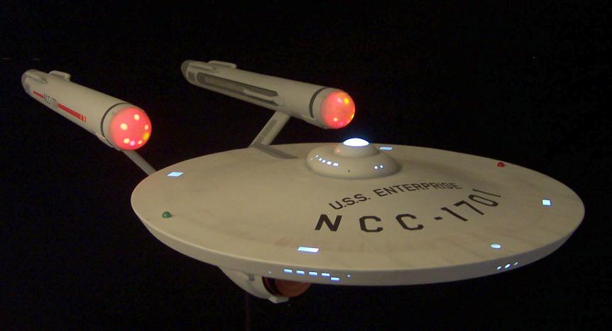
The Master Replicas 1/350 scale TOS Enterprise. I have one of the early ones, number 24.

I refer to it as the tiny E.

Here it is with the Botany Bay, I did the kit years ago with the help of a friend(this kit is still around from what I understand, I no longer have anything to do with it).

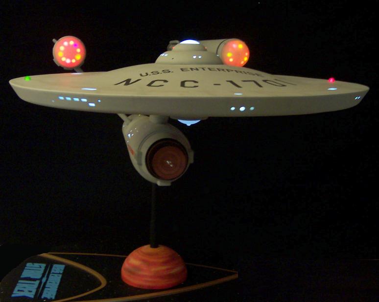
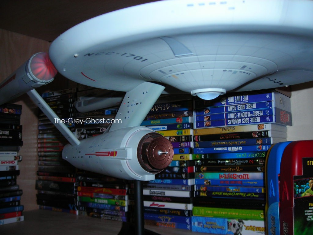
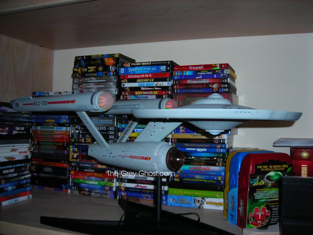
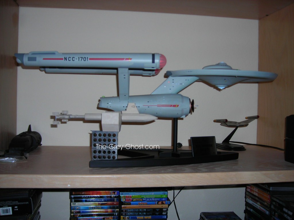
Here it is next to the Custom Replicas 66″ Enterprise.

Hard to believe I’m making something much bigger than these.

The model does have some issues. A lot of the early ones did.

Mine has the nacelle oil issue. It worked it’s way over time.

Sadly it even shows when the ship is off. But I can live with it.

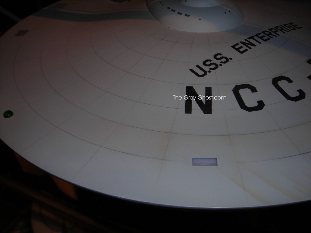
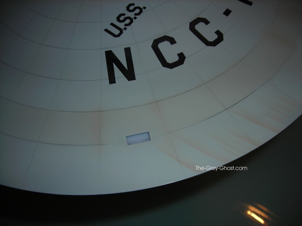
I have a request to show the grid-lines, and here they are.

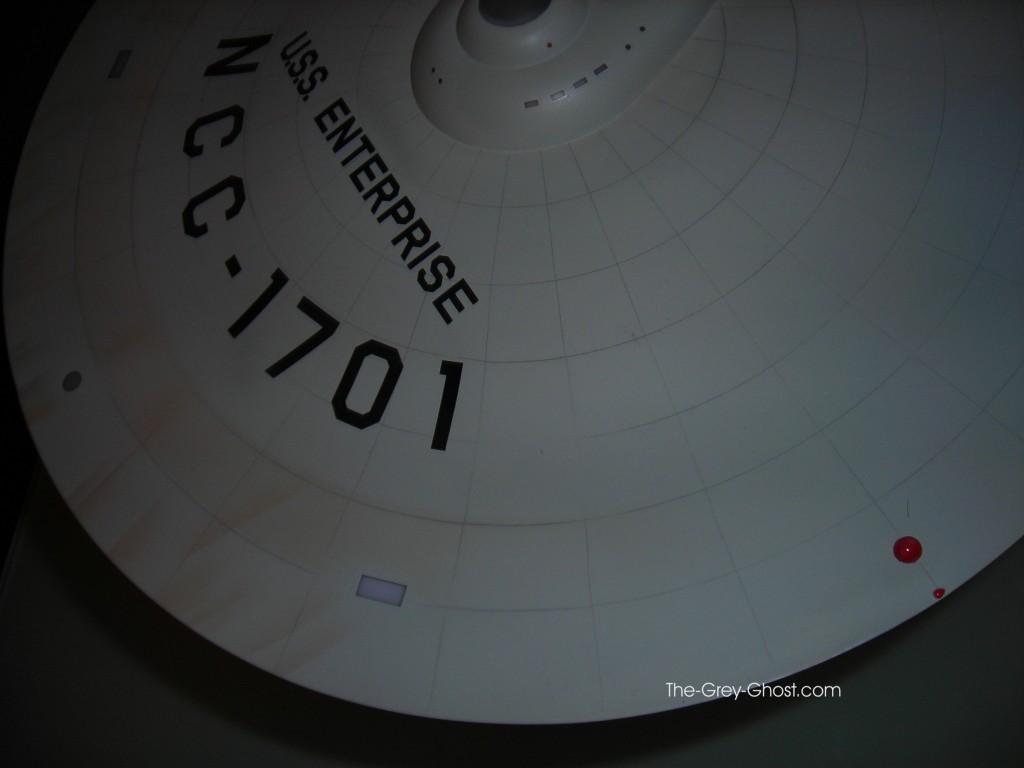
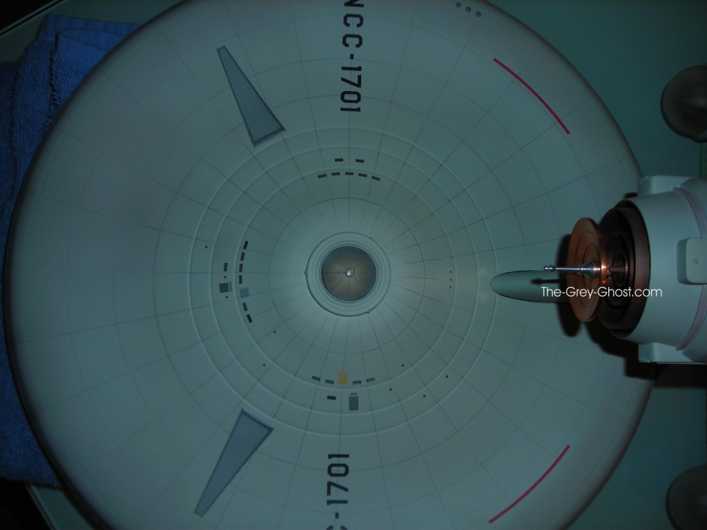
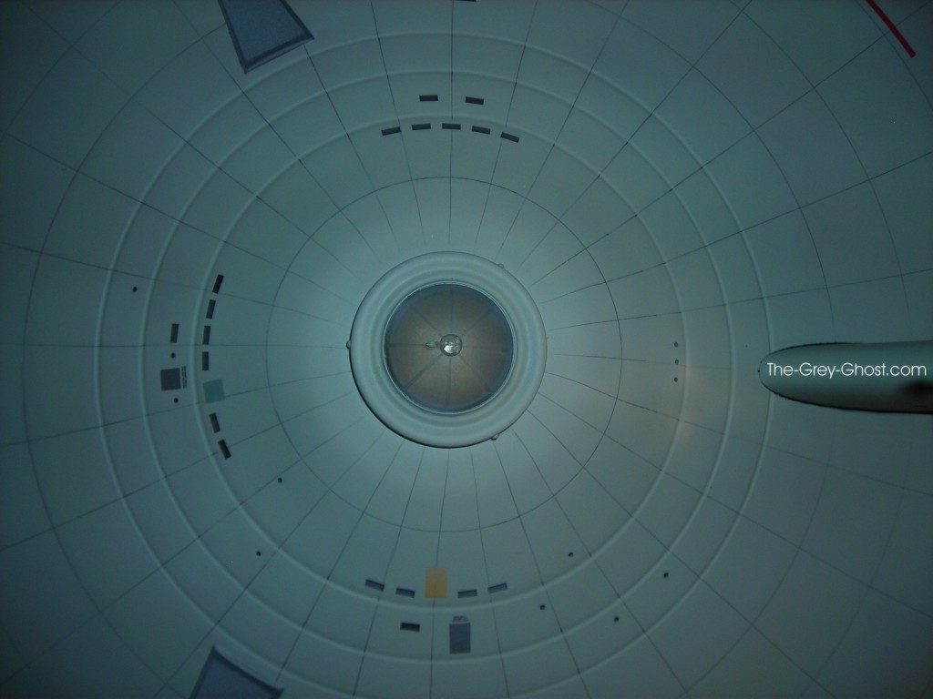
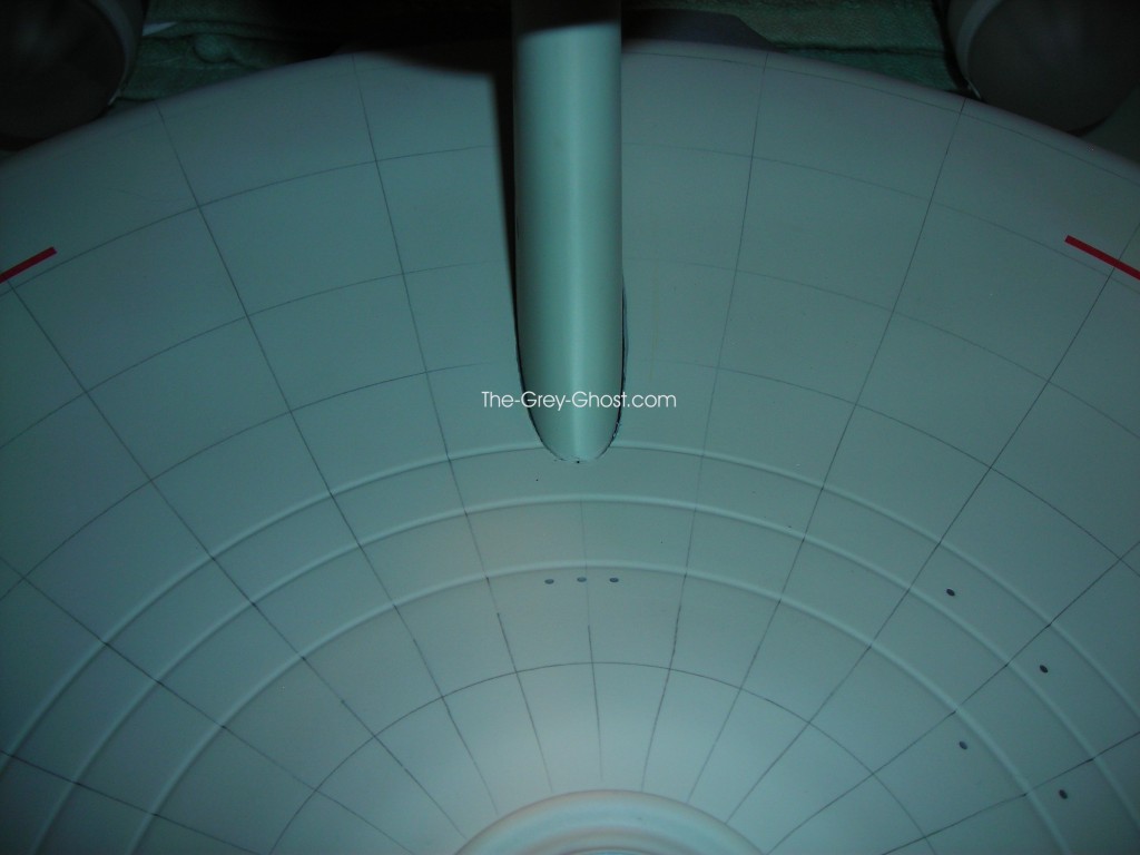
The pics should speak for themselves, they look like they were drawn with a number 2 pencil. The lower saucer grid lines do not go to the center, nor are they straight, and the line quality is very inconsistent. I have a friend that has one. His grids look very different from mine, but the quality is the same.

It is a very neat model, overall I’m very happy with it(and I didn’t have to build it). But I would like to repaint it in the future, because of the quality issues and the over done grid lines.

I”ll post more on this model in the future.

Master Replicas 350 TOS E, Models and Props

Something From Nothing…

Or so it may seem. That is certainly not the case.

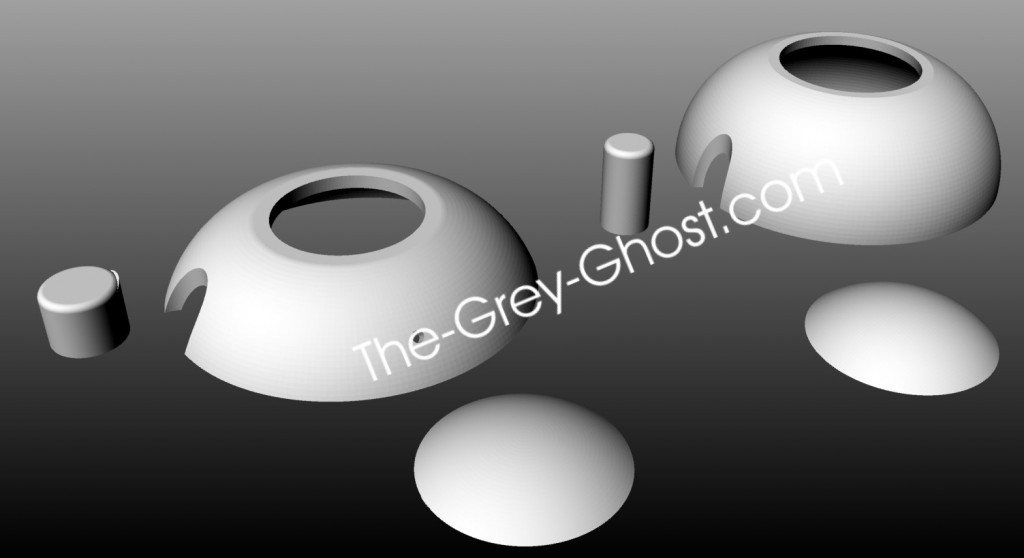
In the last post I mentioned making a 3d model for working out the parts. That’s just the start of the process.

These computer generated parts can be made into real parts.

How?

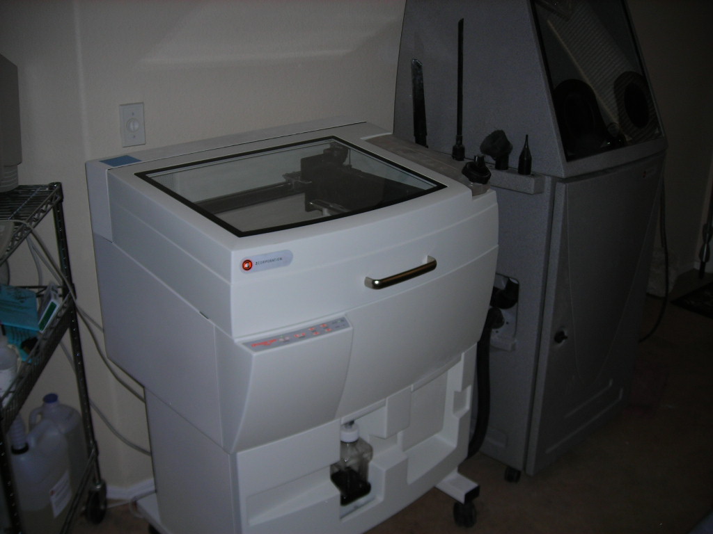
With tools such as-

A three dimensional printer.

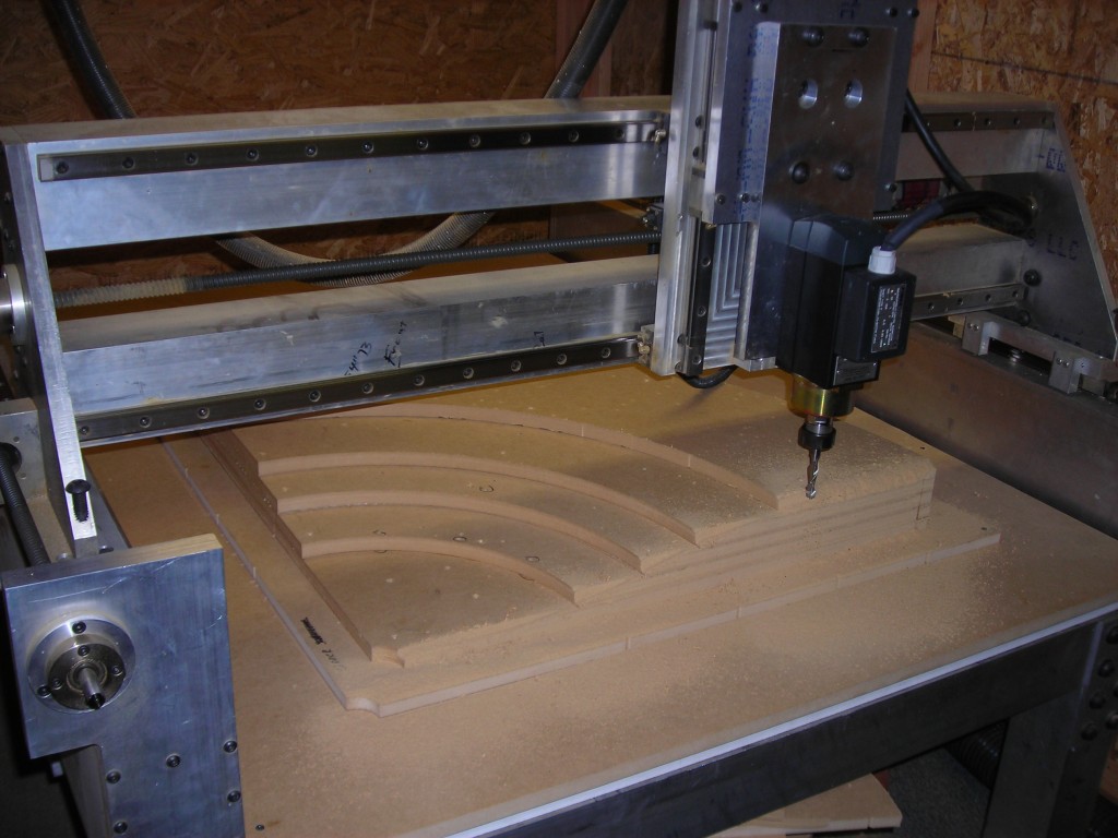
And…

A CNC(computer numerically controlled) router. This machine I designed and built myself.

These tools do not act alone, they need computer’s to run them. And the software and knowledge of how to make these tools work(safely).

What they can do may seem magical.

They can even work together.

One man’s magic is another man’s science.

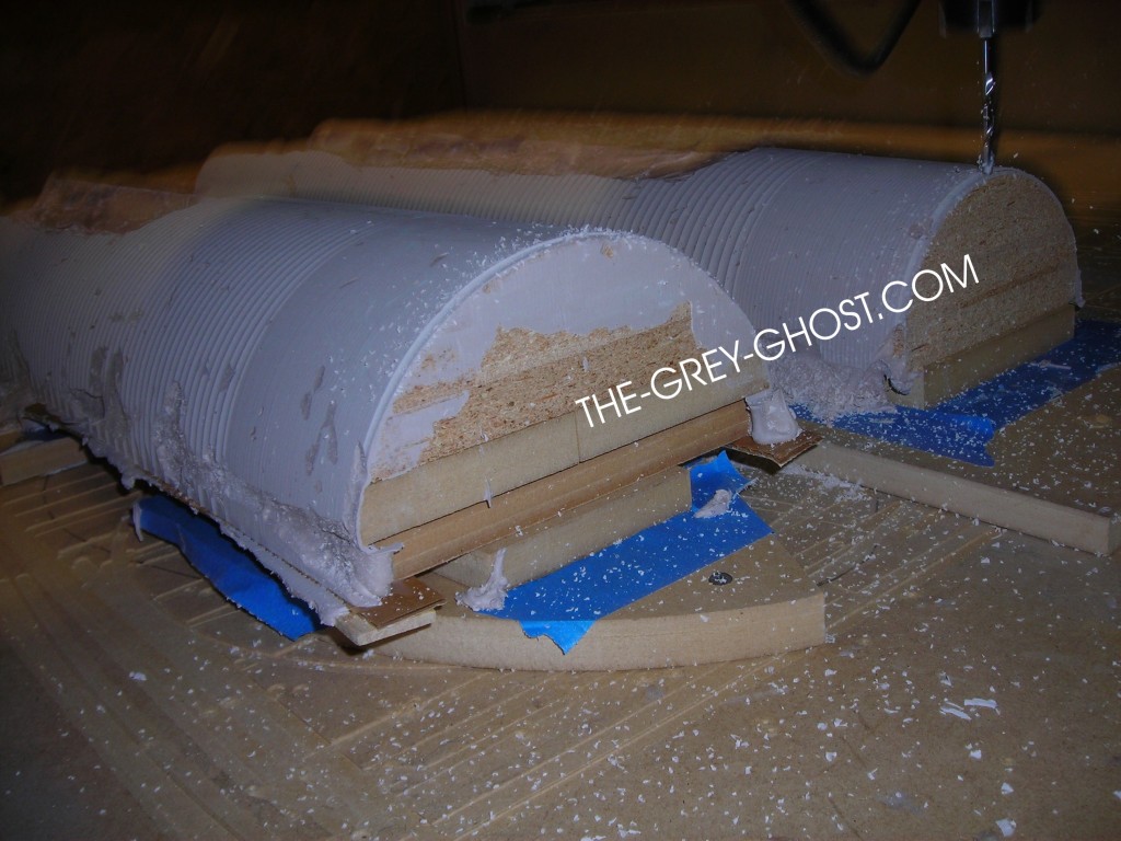
These parts were made on the router. The pic doesn’t show it, but the fit is amazing.
How is this done you ask?

You remember the computer generated model.

This is where it all begins.

The first thing I do is break up the model into pieces that my machines can process. You can’t make a model like this in one shot.

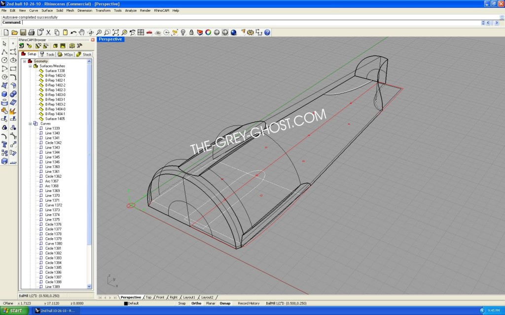
Here is one side of the 2nd hull, in what is called a wire-frame. Wire frames take up less system resources, and it shows it the base drawing beneath.

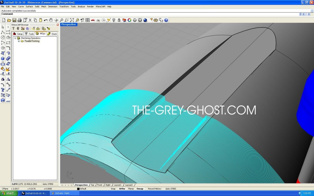
That part/model is used by the software to create what is called a toolpath. A toolpath is a set of instructions that tells the router what shape to cut. This is the stage where I can control how fine the machine will cut the part. That is done by telling the software to cut the part at a set distance. It’s the same thing as making profiles and filling in between them. Only the machine can turn the part into thousands of profiles, and do it more accurately than any human ever could.

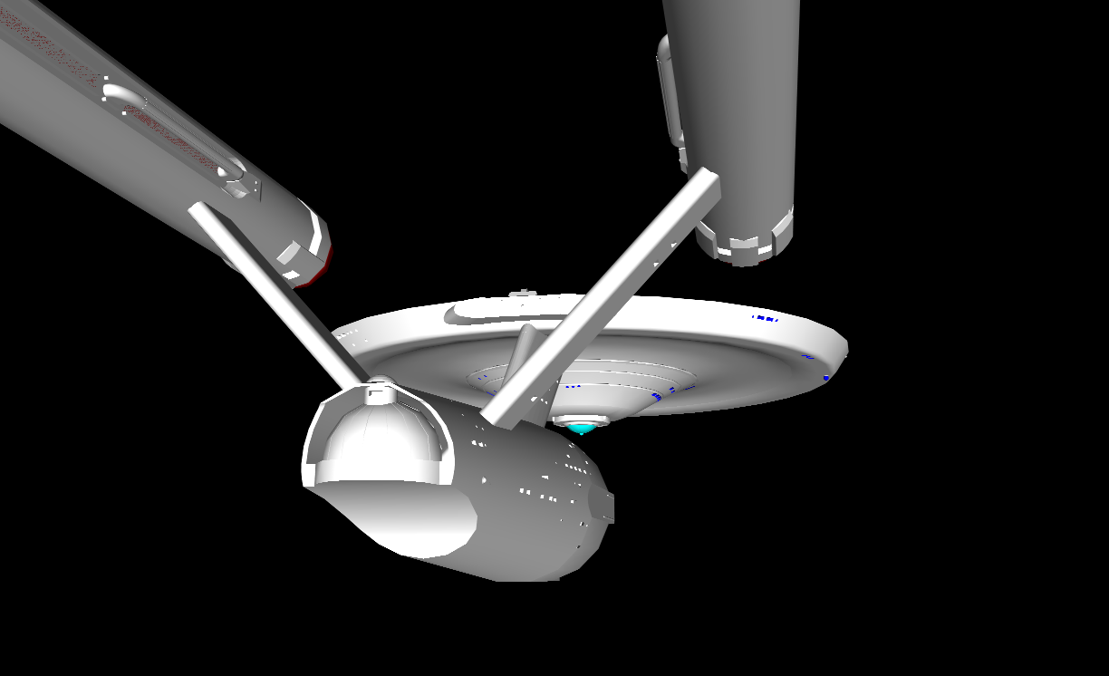
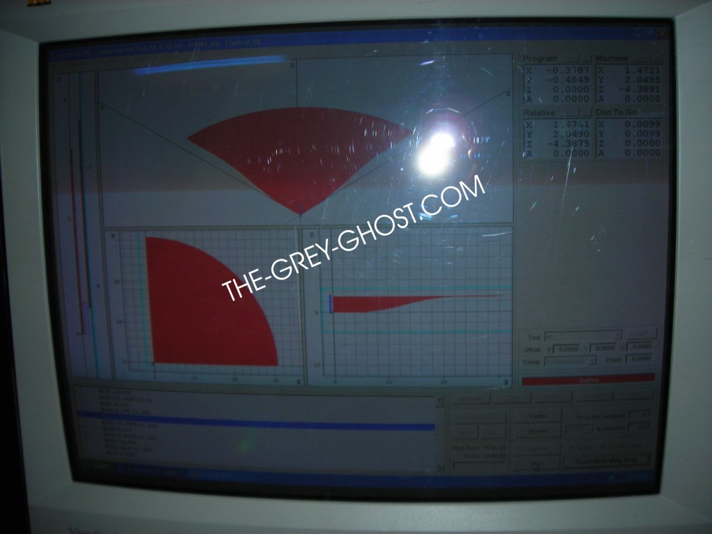
This is an example of the control screen for my router. If you can see it this part is set to run for over 30 hours. That means I’m making the surface as fine as I can. Or what is called a finish pass. To give you an idea of what that means, if I set the machine to cut at .01″ the router will make 100 passes in 1 inch.

This is an example of the machine in action. It’s just starting a finish pass on the nacelle, it does have to be run again. But that’s of little concern to me, since the machine runs automatically. But it can screw up, and so can I(we are all prone to that).

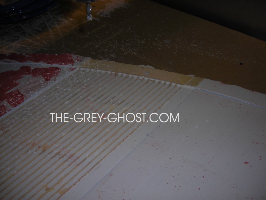
This is an example of the machine screwing up. Notice the tan lines through the part. They are not supposed to be there, the router’s software is cutting the part to low. This happens on occasion it’s just part of doing this stuff, the software gets a glitch and I have to start over.

Printed parts are similar up to the model stage.

How they are created is a little different. Printed parts have less limitations as far as things like undercuts. But you can add more detail, holes, etc.

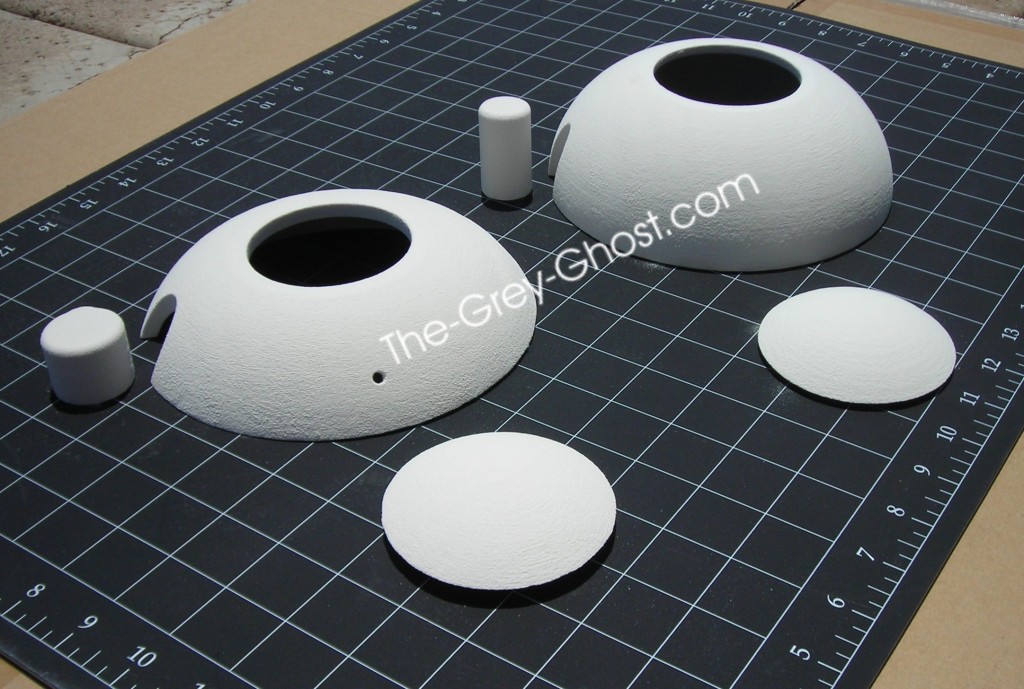
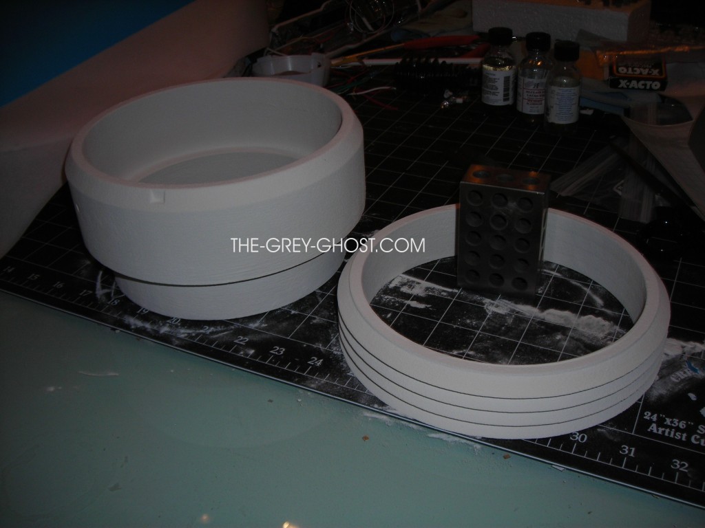
These parts(bussard mount) were printed, they could have been done as one part. But it’s easier for casting and final assembly to make them two pieces.

But you can’t just print the parts, and your done(I only wish). The parts have to be finished, at this stage they are not very strong, and they need to be cleaned up. If you look at the parts closely you will see the layers that make up the parts. These have to be filled and smoothed out.

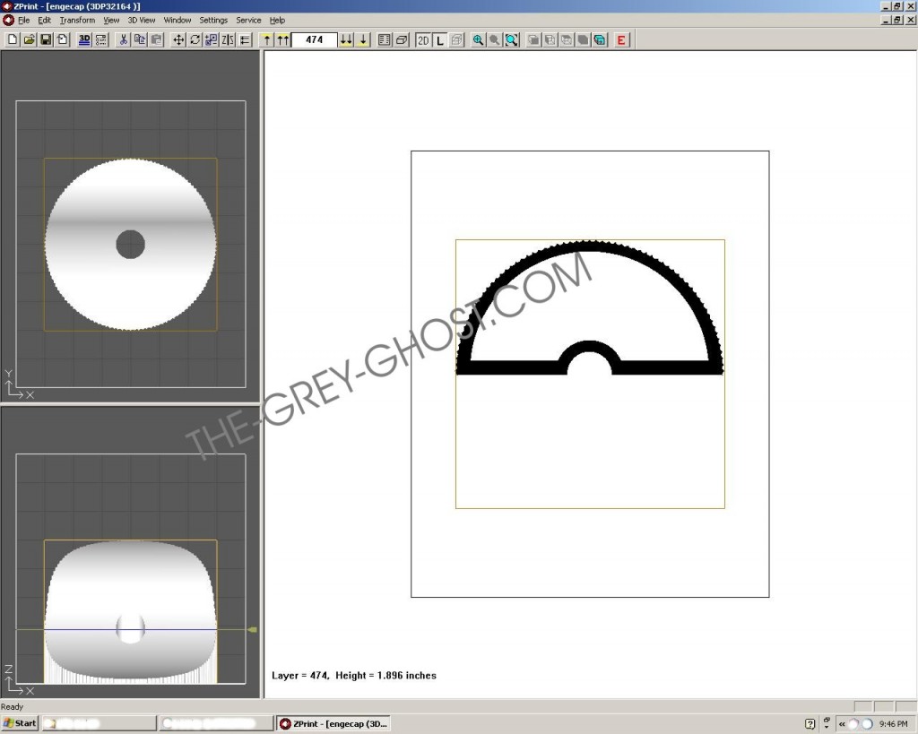
Here is why, this is the software that controls my 3d printer. It builds the part in layers, in this case each layer in .004″ thick. It’s very powerful and some of the simplest software I’ve ever used. But it comes at a price, you have a lot of work on the other end. The same thing thing goes for parts that come out of the router. No matter how fine I make the part, it still needs to be finished. That is why this stuff is done to make the next step easier.

More to come…


Studio Scale Models, Studio Scale TOS Enterprise(11.25 feet)

NOMAD

I’m sure you guys remember this prop.

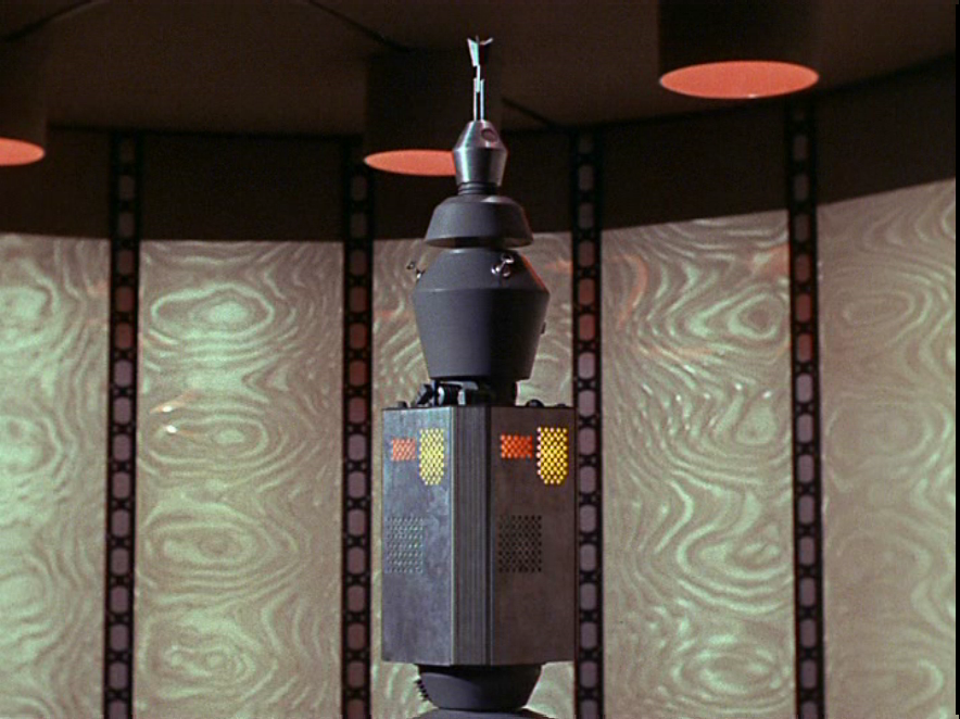
I did my best to recreate the prop back in 2005.

This was the result.

The effort was exhaustive, I used only screen caps of the prop. If I saw a part in at least 2 different scenes it ended up on the model. This is a very hard process especially since there is no way to get any actual measurements of the prop. I assume the prop was cannibalized/destroyed and is now somewhere in the bottom of an LA landfill. So it’s all guess work from start to finish.

Where do you start?

One thing a lot of guys do is go by the, “fraction over one meter” Spock stated. That line is about as nebulous as you can get, it’s of no help. I would not recommend using it, your prop will be undersized.

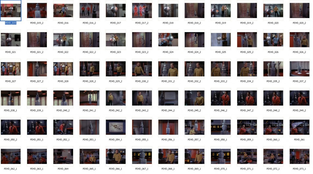
Reference. You get pics galore, every time the shot changes you get as many screen grabs as you can.

It does get a little tedious, but it’s the only way to get what your looking for(this is only a part of my screen grabs).

But once you have something to work with. I can say it’s easier and harder at the same time. These screen grabs are from the DVD, I think that’s all that’s necessary. The STTOS props were simple when compared to the later movies/series. If you look at something long enough your going to see things that are not there. That’s why I have a rule of seeing a part in at least 2 shots. The eye will play tricks if your not careful, and I’ve seen a lot of guys swear by stuff that isn’t there(and not just in this hobby).

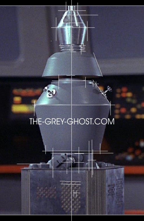
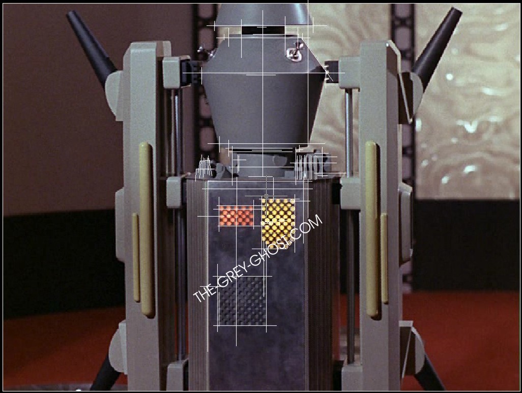
First thing I do is import images into Autocad. Then I select a part and make an educated guess as to how big it is.

I eventually came up with 3″, it’s the part below the crown and above the head. From there I have to guess everything else, I try to keep the numbers as even as I can. Other things I’m looking for are angles and part relationships. This part is hard to get right, these props are almost never photographed head on, even if they are then the camera can distort things. What I do is look for straight lines then play with the perspective.

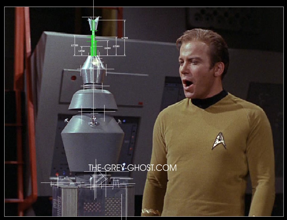
With all apologies to Bill Shatner, sometimes you catch some funny stuff.

But once you establish a center-line on the prop, things can get a little easier. But it’s still all guess work.

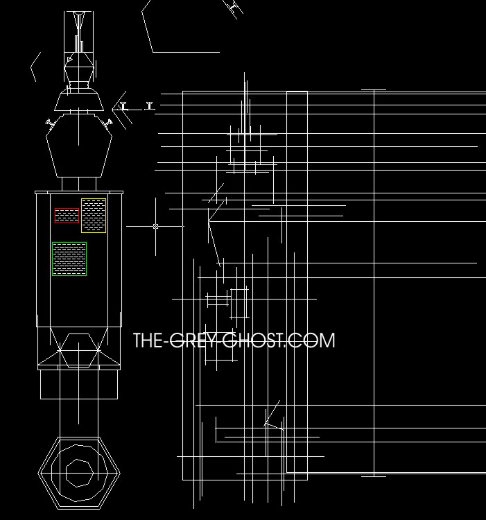
One of the nice things about being able to place an image in CAD, is being able to draft right on top of it. It makes life a lot easier than having to translate between mediums.

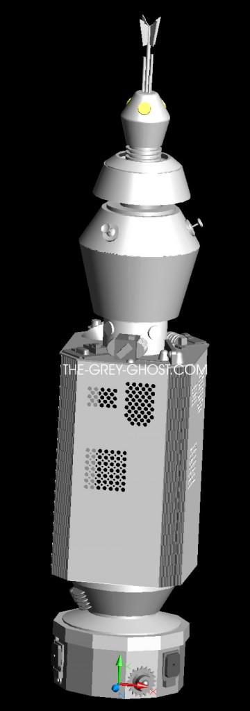
All the while I’m going over images I’m creating a base model.

Which looks like a total mess.

That’s how these things come together, at least for me.

But the end result is worth it.

Now I have something to work with.

But once I have a CG model, the work is only just beginning.
This model is destine for 2 things.

1, A set of plans for others to follow.

2, A full scale model for myself.

The plans got around, that’s why I made them.

There is good and bad with sharing such work. Some are very happy and appreciative to see such work, while others seek it out for personal gain.  I learned my lesson on this one, while it’s very high and noble to share, that usually isn’t what happens. Those who seek personal gain are the only one’s who get to profit off of others good will.

Since I made the plans in 2005, I’ve been wanting to update them. Since I came across new info.

I did make one request for those who use the documents(plans). I wanted pics of your work, to date I haven’t received a thing. But I have seen plenty of you using my plans.
There is more to come(I’ve got to show you guys the finished prop).


Models and Props, Nomad

Space is the place.

Continued from the previous post.

After the plans are in order(I still tweak things as I go) , I see if things will work on the model by creating a 3d model out of my plans.

I did this years ago, whenever I make a 3d model I make it to work out the parts. I don’t bother with graphics and such at this stage.  That stuff is easy when compared to the model itself.

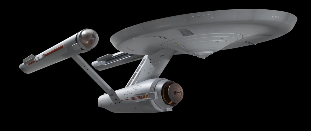
I still can’t resist the beauty shots. When making a 3d model it allows me to do some really neat things in the real world.

WARNING: This is where things get interesting.
My first concern with taking on such a project is space.
Space to fabricate parts, space to paint the parts, and lastly space to display the model.

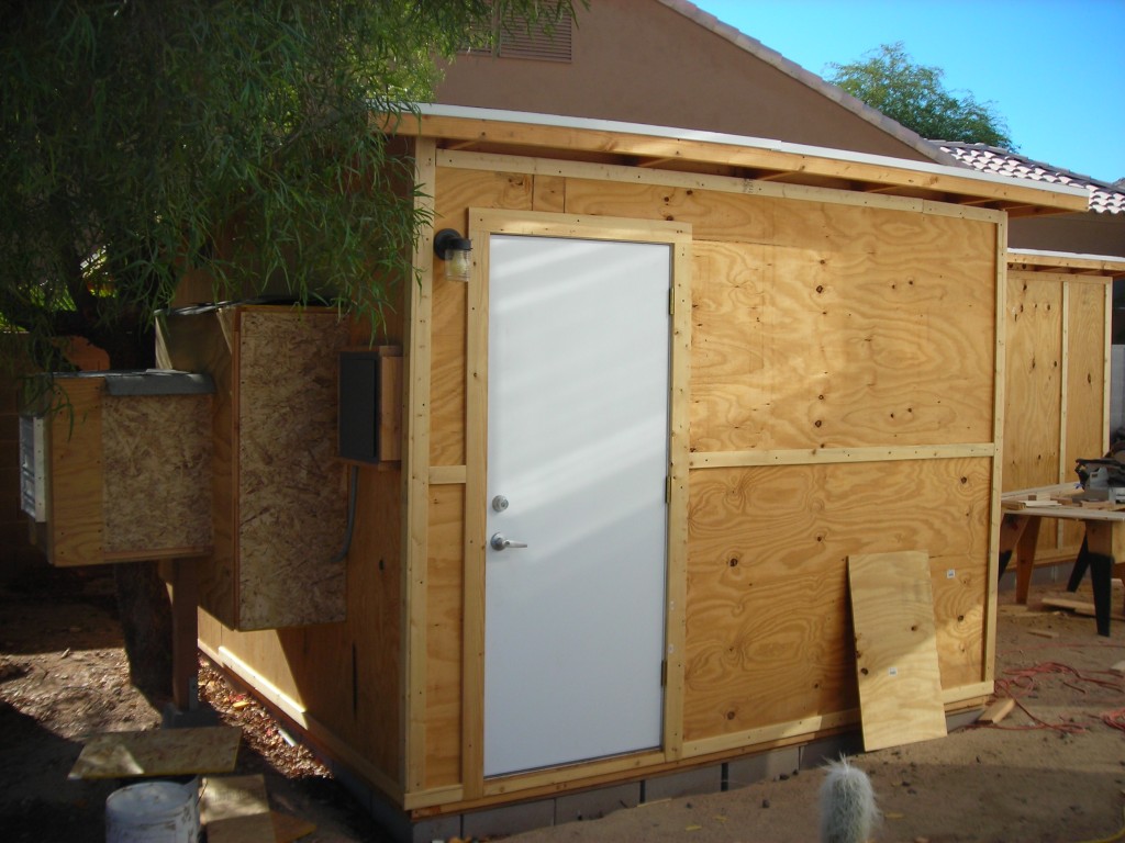
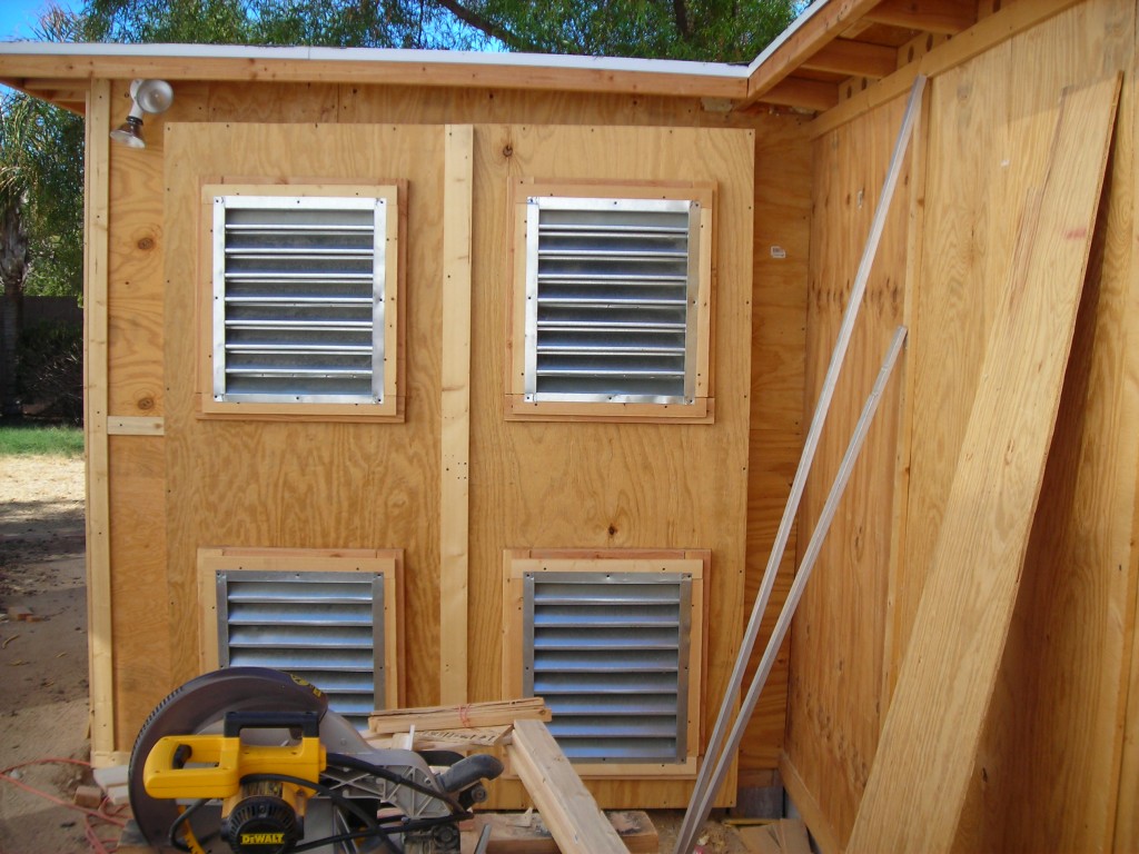
We needed some additional storage and getting tired of paying for a mini storage. Plus my Wife would like me to have a dedicated space to paint things(our last house got a bit messy because of my painting). So I designed and built a shed with a paint booth on the side.

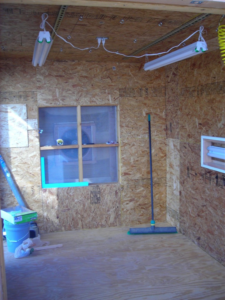
It has an explosive proof fan with controls on the outside. Note the door position, it’s placed almost next to the the interior intake of the fan. So any dust or whatever will hopefully not make it’s way to anything I’m painting in there.

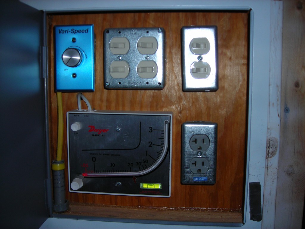
This is the control box, the meter is called a manometer. It tells me when I need to change the filters(besides looking at them). The switches are lights and the dial in upper left corner is the fan control.

These are the exterior intakes, I originally designed it as a set of doors. But that didn’t work so well(I turned them into a wall). I thought anything painted in there should be able to go through a door. Otherwise it’s never going to get in the house.

Here is the interior, it still needs to be painted. Note the ceiling it has hooks and rails for hanging parts. The fan is in the center of the image. The framing is for the filters, and there is 1/2″ screen to keep the filters in place.

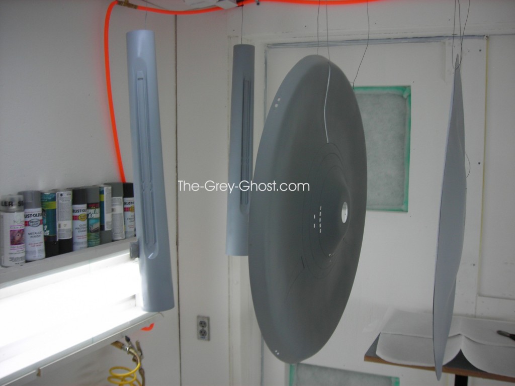
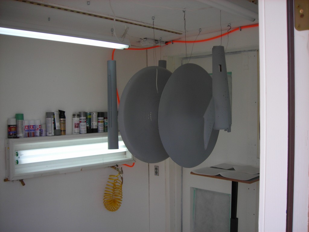
Here is a shot of the interior. With my Little E(66″) being primered and you can see the hooks in use(the parts are drying in this pic).

The interior is painted white, with 4 sets of lights two fixtures on top and one on each side. The florescent orange hose is the air line, that’s used for airbrushes, paint guns, and for general clean-up(lol).

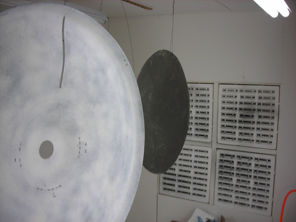
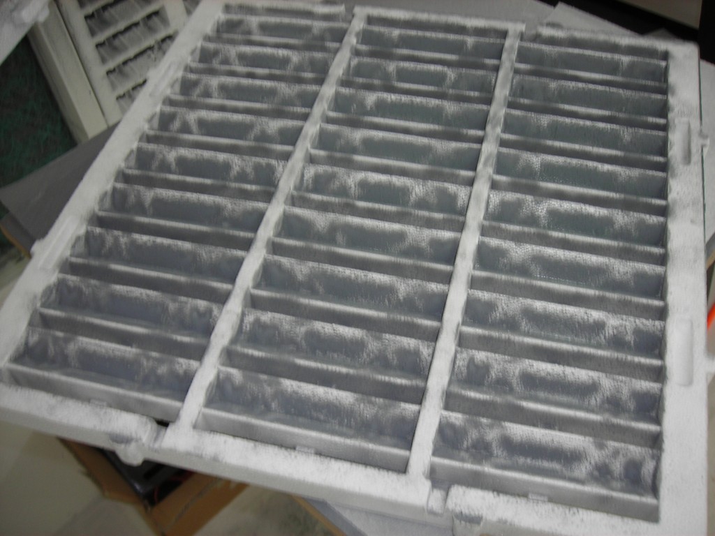
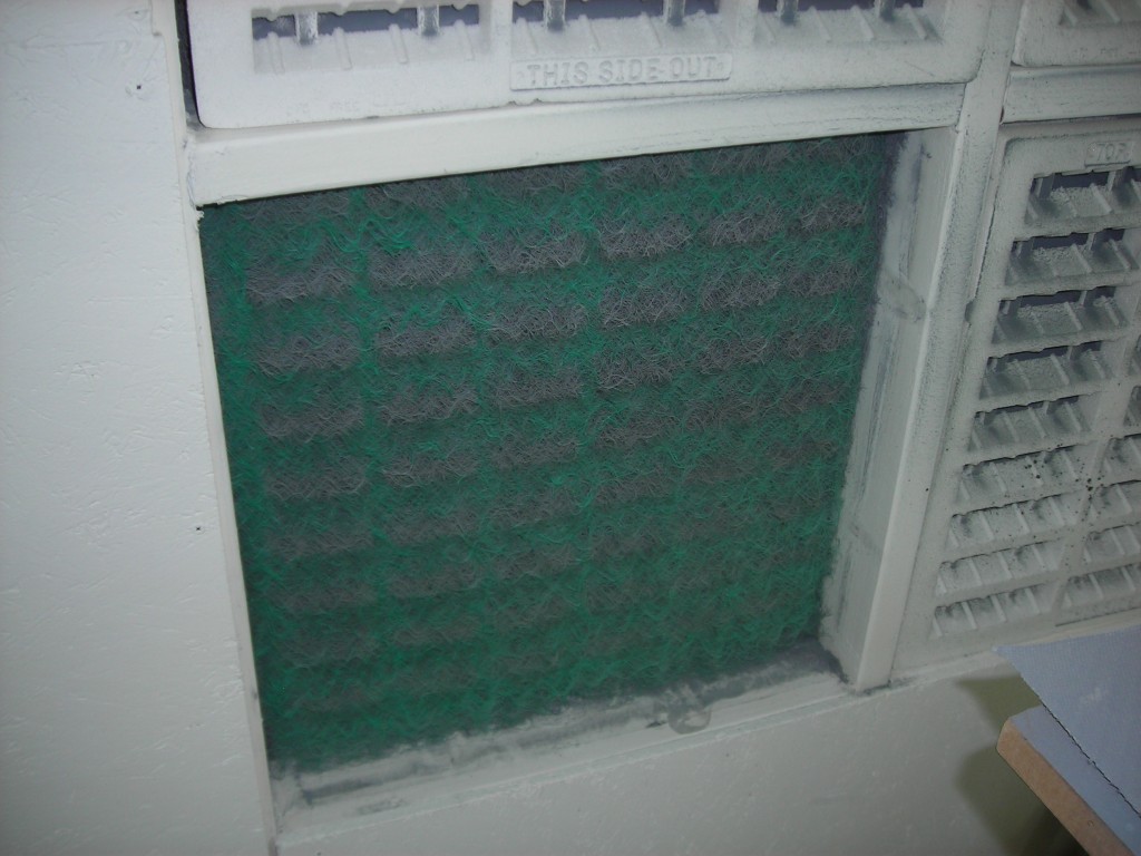
This view is toward the front. The filters are behind the paint arrestors(styrofoam grills) they help keep paint overspray out of the filters beyond.

They can get a bit messy.

Imagine the filter beyond if I didn’t have arrestors.

Since the booth relies on outside air, I have to watch the temperatures when painting.
That doesn’t bother me, in Arizona that’s just how things are.

I’ve got plenty to do indoors.

The next place that needed my attention was the garage or my shop(if you like).

Sadly I don’t have any pics of my shop during this time. But then I’m sure most of you can imagine a workspace such as mine, stuff and dust everywhere.

Cleaning it is a chore to be sure, except for the occasional find of treasure. I’m sure I’m not the only one that exclaims, “I didn’t know I had one of those!”.

That’s it for now.

Any questions, comments?


Studio Scale TOS Enterprise(11.25 feet)

To Boldly Go…

Where No Man Has Gone Before.

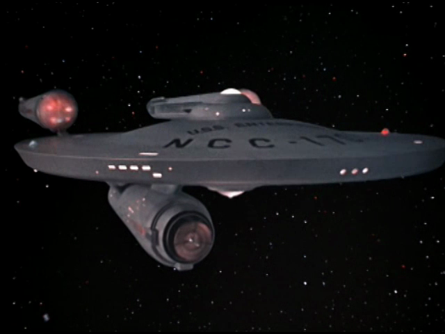
Well, not exactly. There have been many models of the big E in many different scales.

But in studio scale?

Not many models would come bigger.

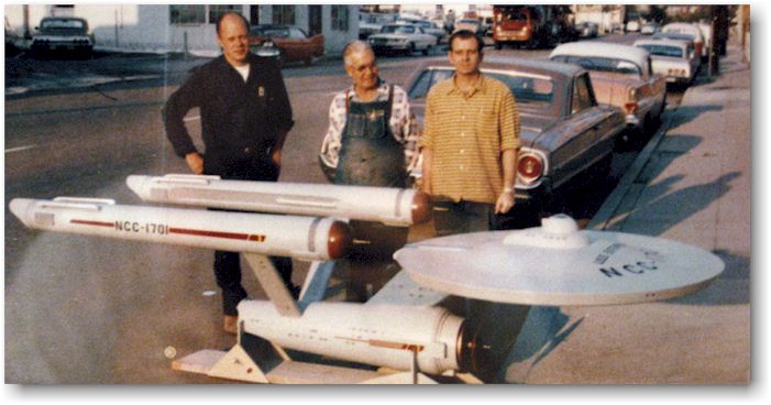
The Studio Scale Enterprise is over 11.25 feet long.
That’s 141 inches in length, 60 inches in width, and about 36 inches high.
I’m building the pilot and production versions for myself. I’m thinking of offering build-ups, kits wouldn’t be very realistic since the price would be in the 5 figures. Of course build-ups will be far more than a kit, such things are very expensive and time consuming to make. As I will show you in future posts.

How do you start such a project?

You start with drawings and reference.

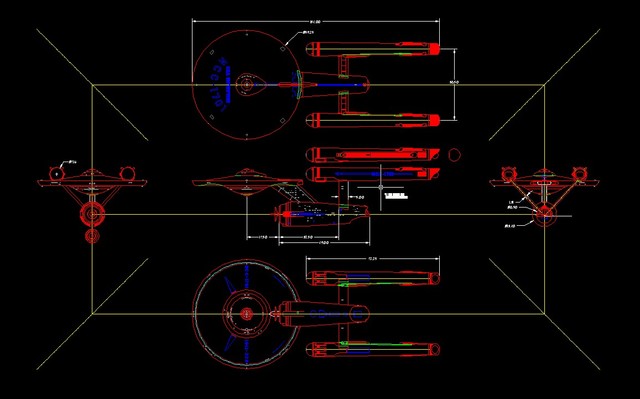
Years ago I found Alan Sinclair’s drawings.

http://www.angelfire.com/scifi2/wizardofflight/TOS1701.html

Those were great, I was so happy somebody made something of the Big E available. They were in a file format I could use(Autocad) So I used those as a base.

After many years of working my way around the hobby. I finally got to see the drawings that were the basis of models such as the Master Replicas 1/350 Scale E.

And was disappointed.

This is not a knock against the guy(Gary Kerr) that created the drawings. He did his job very well, so well he got truly accurate drawings of the original studio model.

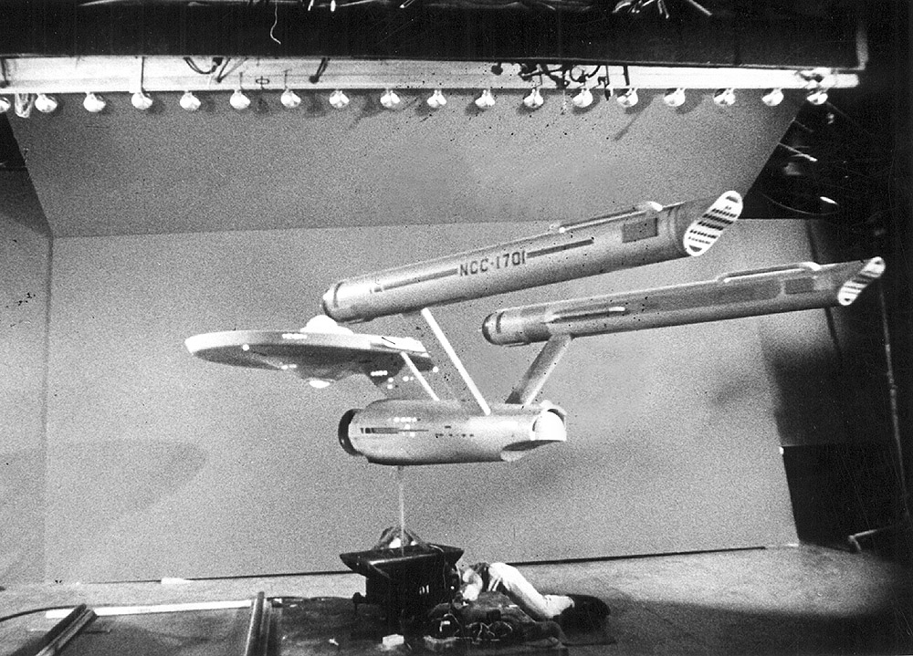
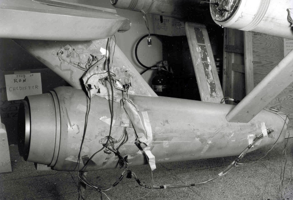
Now studio models are not perfect, in fact they are as far from perfect as you can get. They are meant to look good on screen, and that’s it. They are made on a budget, and a deadline. There is no time to get things perfect, most studio models will never meet the perception of the viewer. The E is no exception to this.

As you can see, this side of the ship wasn’t meant to be seen. Which I hope makes my point.

I did a comparison to the Sinclair drawings. Are what I would call eyeball close, I’m sorry I can’t post the comparisons. I wish I could but I’m sworn to keep the drawings out of the pubic eye. I have no problem with that, because such things are people’s lively hood. If we as modelers want more models in the future, then it’s best to leave such things to those who produce models.

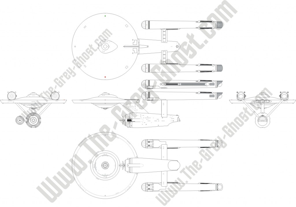
What I can show you is a hybrid of each of these drawings along with my tweaks to make things meet my perception of the E.

These are not done, but it does give an idea of where start this process.

As far reference goes, there is a lot of helpful stuff out there. But I wouldn’t go by the restored(re-imagined) E at the Smithsonian. The differences are very stark-

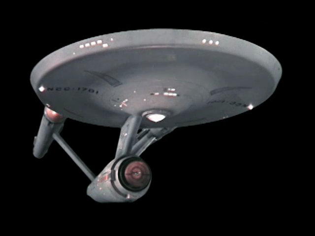
Same model different paint jobs.

Sadly the lower pic is the Big E in her current state. Which doesn’t meet my perception of the Enterprise(it doesn’t meet a lot people’s perception), it’s not only a bad paint job, but it fails one other aspect. It’s not what people saw on the show, that was the biggest mistake. I consider it thumb in the eye of Trekkies everywhere, for at the very least the most iconic ship/model in all of science fiction was treated with such little respect. The ship should be in the state as it was filmed, because of it’s historical place in science fiction.

There is more than just a poor paint job.

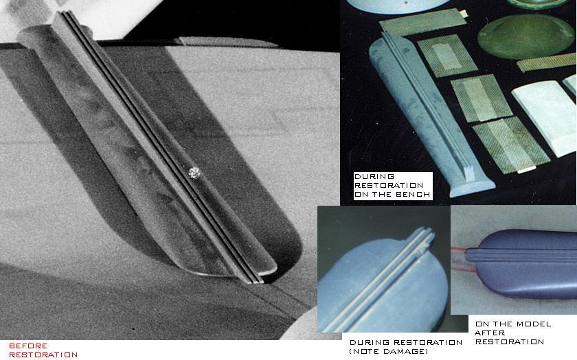
This is a composite I made of the accelerator, note the changes made during the restoration. Some will say it’s not a big deal, others like myself consider it a big no-no to do this to such an artifact. I would urge anyone in a position at the Smithsonian, to please do something to restore the ship to it’s original state.

Why did I bring this up? To show that not all reference is credible, and again it’s one’s perception. Do they want to make the ship look like it’s current state? That’s one’s choice, personally I wouldn’t want the extra work.

Now I never said this is going to be accurate model of the E. I would never make such claims with any model, but I do question those that do make such claims. Because you can never have an absolutely accurate model(unless you obtain the original model). Besides these things are all perception, I’m going to spot things you won’t and vice versa.

There is much more to come.


Studio Scale TOS Enterprise(11.25 feet)