Or so it may seem. That is certainly not the case.
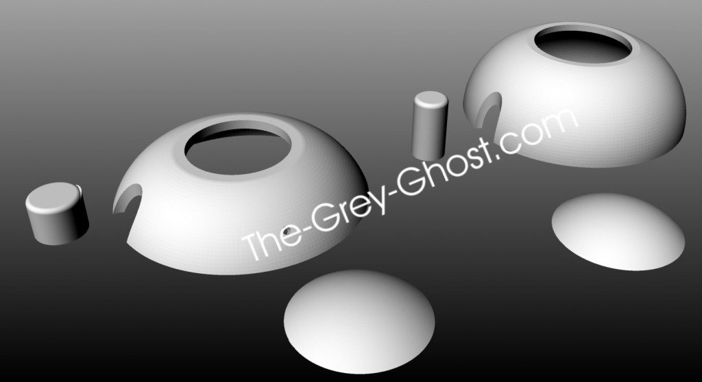
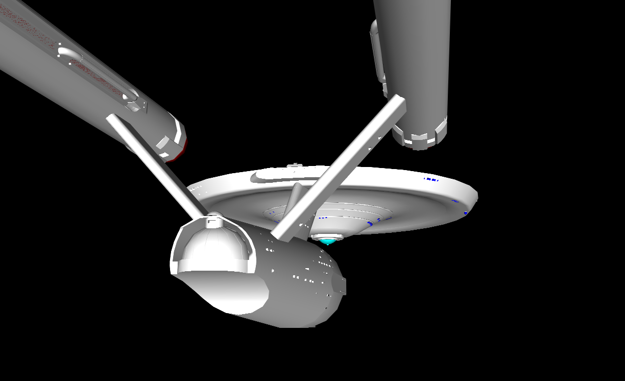
In the last post I mentioned making a 3d model for working out the parts. That’s just the start of the process.
These computer generated parts can be made into real parts.
How?
With tools such as-
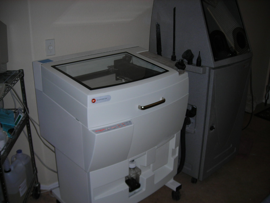
A three dimensional printer.
And…
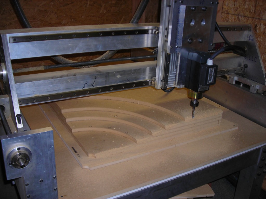
A CNC(computer numerically controlled) router. This machine I designed and built myself.
These tools do not act alone, they need computer’s to run them. And the software and knowledge of how to make these tools work(safely).
What they can do may seem magical.
One man’s magic is another man’s science.
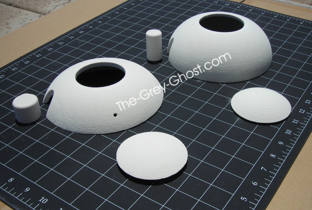
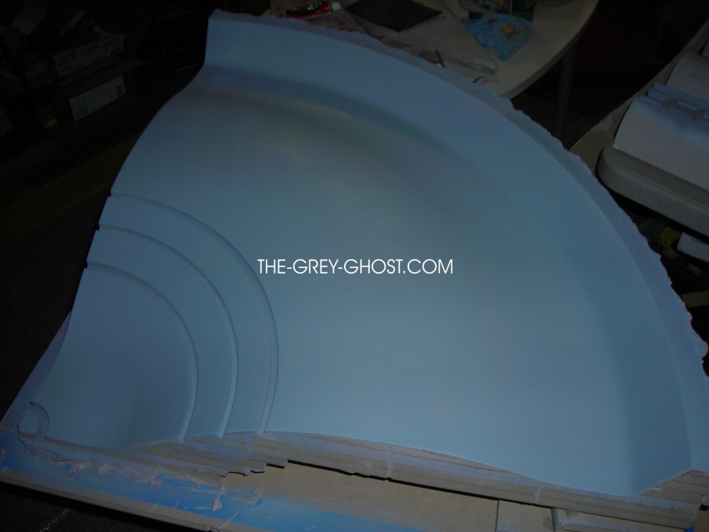
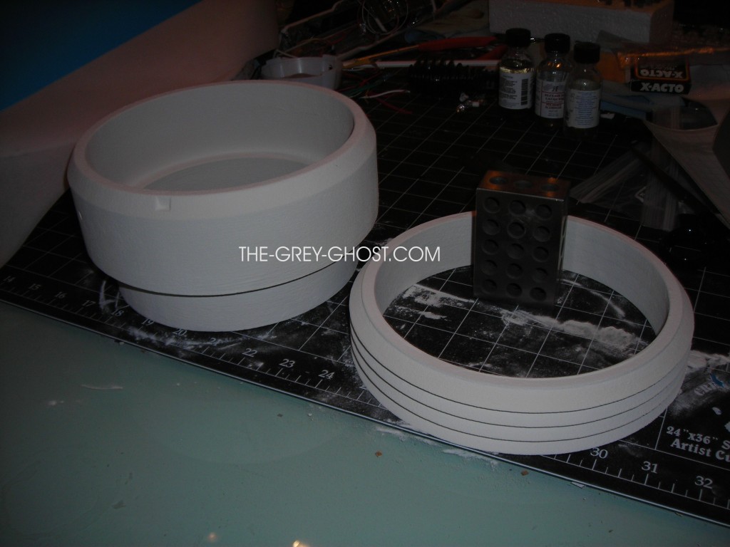
These parts were made on the router. The pic doesn’t show it, but the fit is amazing.
How is this done you ask?
You remember the computer generated model.
This is where it all begins.
The first thing I do is break up the model into pieces that my machines can process. You can’t make a model like this in one shot. 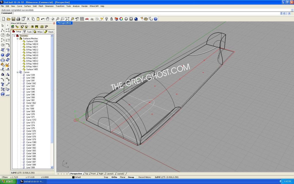
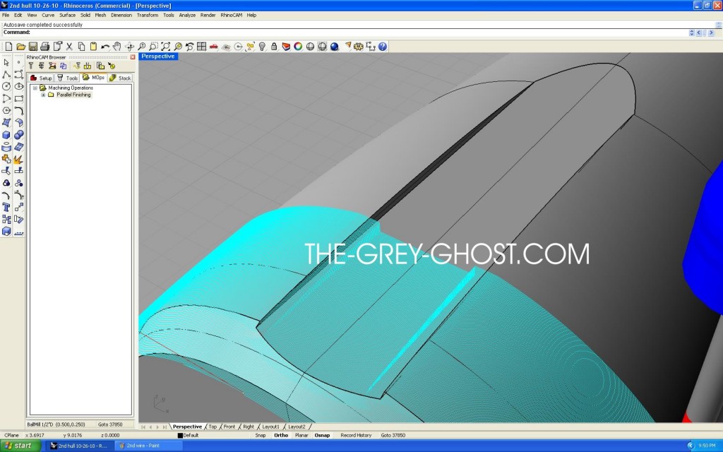
Here is one side of the 2nd hull, in what is called a wire-frame. Wire frames take up less system resources, and it shows it the base drawing beneath.
That part/model is used by the software to create what is called a toolpath. A toolpath is a set of instructions that tells the router what shape to cut. This is the stage where I can control how fine the machine will cut the part. That is done by telling the software to cut the part at a set distance. It’s the same thing as making profiles and filling in between them. Only the machine can turn the part into thousands of profiles, and do it more accurately than any human ever could.
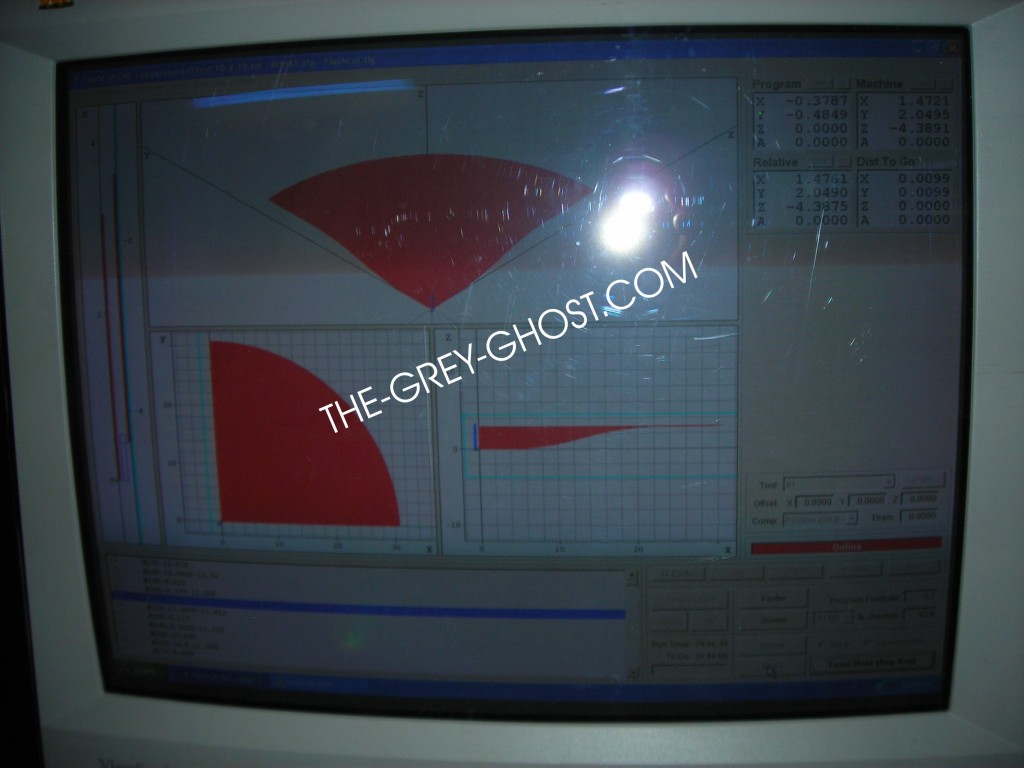
This is an example of the control screen for my router. If you can see it this part is set to run for over 30 hours. That means I’m making the surface as fine as I can. Or what is called a finish pass. To give you an idea of what that means, if I set the machine to cut at .01″ the router will make 100 passes in 1 inch.
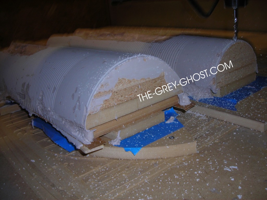
This is an example of the machine in action. It’s just starting a finish pass on the nacelle, it does have to be run again. But that’s of little concern to me, since the machine runs automatically. But it can screw up, and so can I(we are all prone to that).
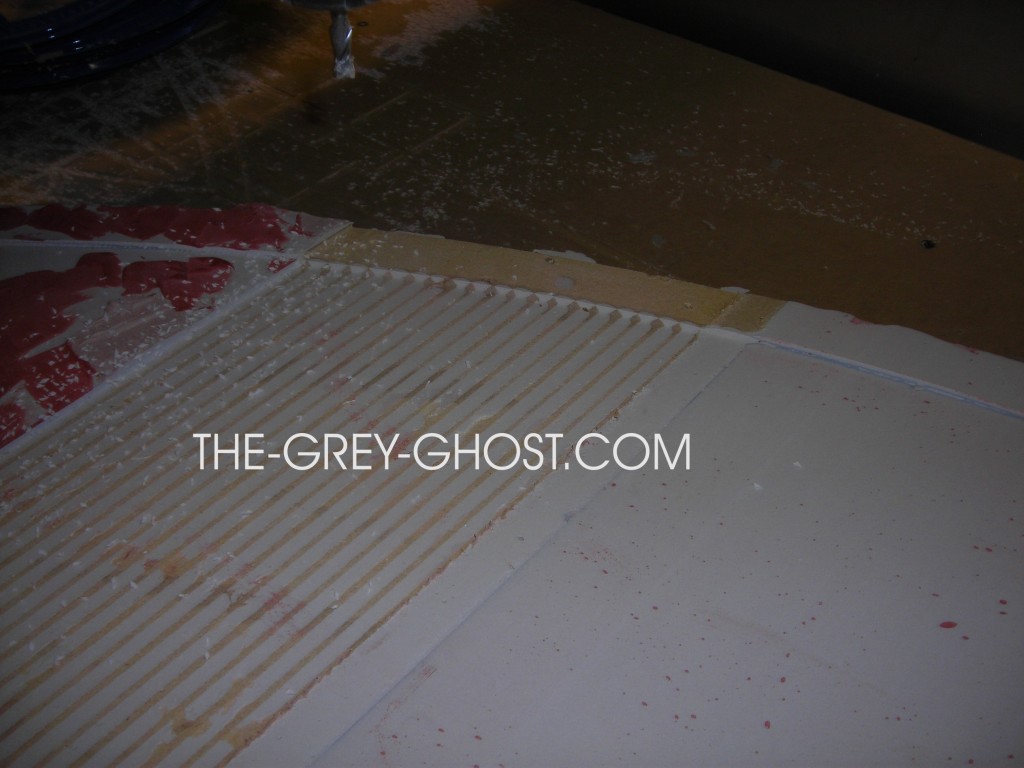
This is an example of the machine screwing up. Notice the tan lines through the part. They are not supposed to be there, the router’s software is cutting the part to low. This happens on occasion it’s just part of doing this stuff, the software gets a glitch and I have to start over.
Printed parts are similar up to the model stage.
How they are created is a little different. Printed parts have less limitations as far as things like undercuts. But you can add more detail, holes, etc.
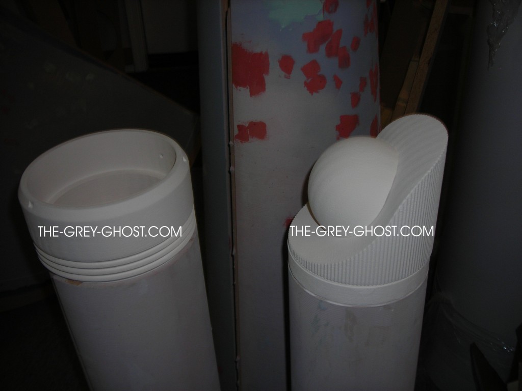
These parts(bussard mount) were printed, they could have been done as one part. But it’s easier for casting and final assembly to make them two pieces.
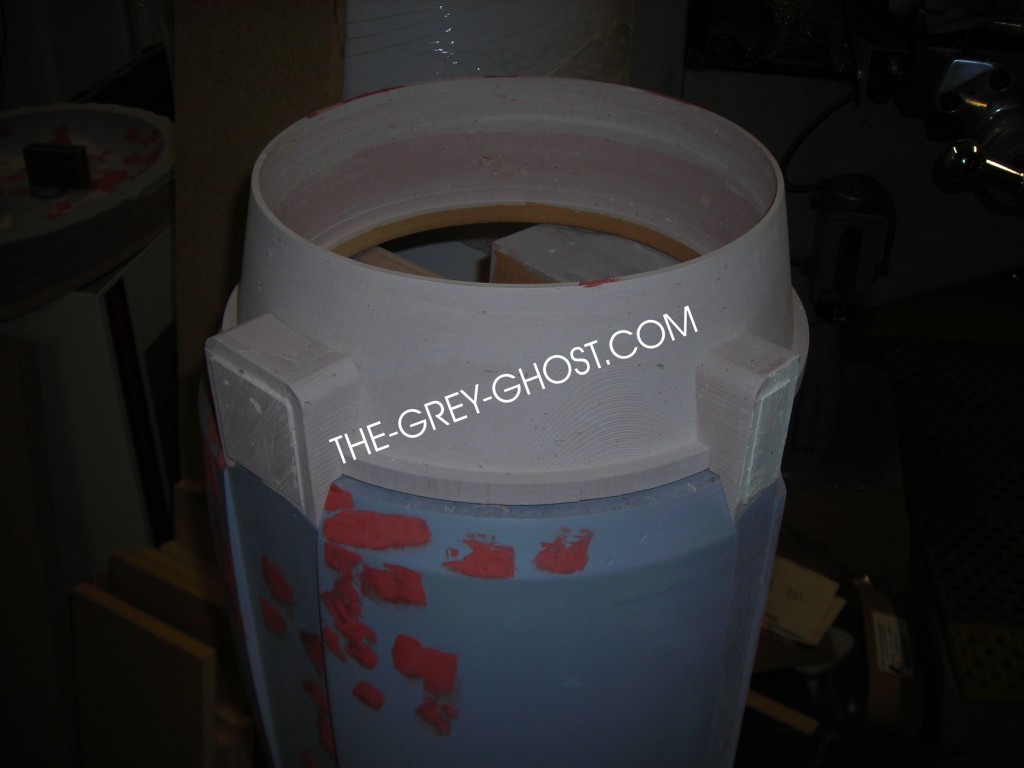
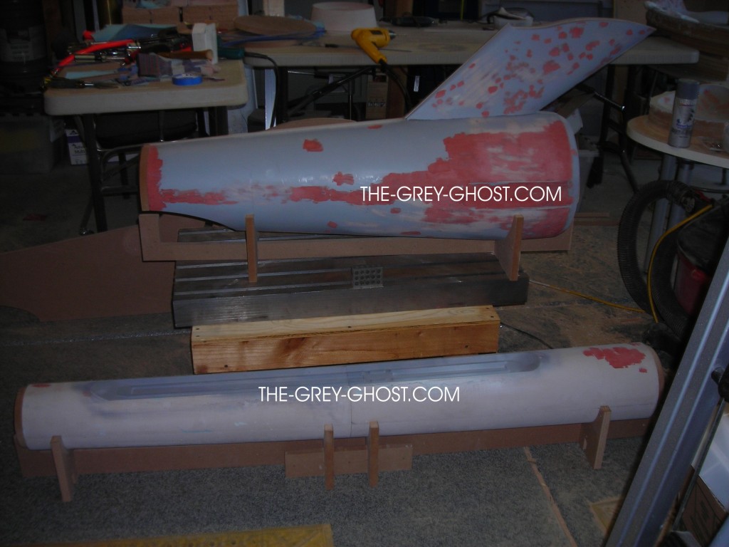
But you can’t just print the parts, and your done(I only wish). The parts have to be finished, at this stage they are not very strong, and they need to be cleaned up. If you look at the parts closely you will see the layers that make up the parts. These have to be filled and smoothed out.
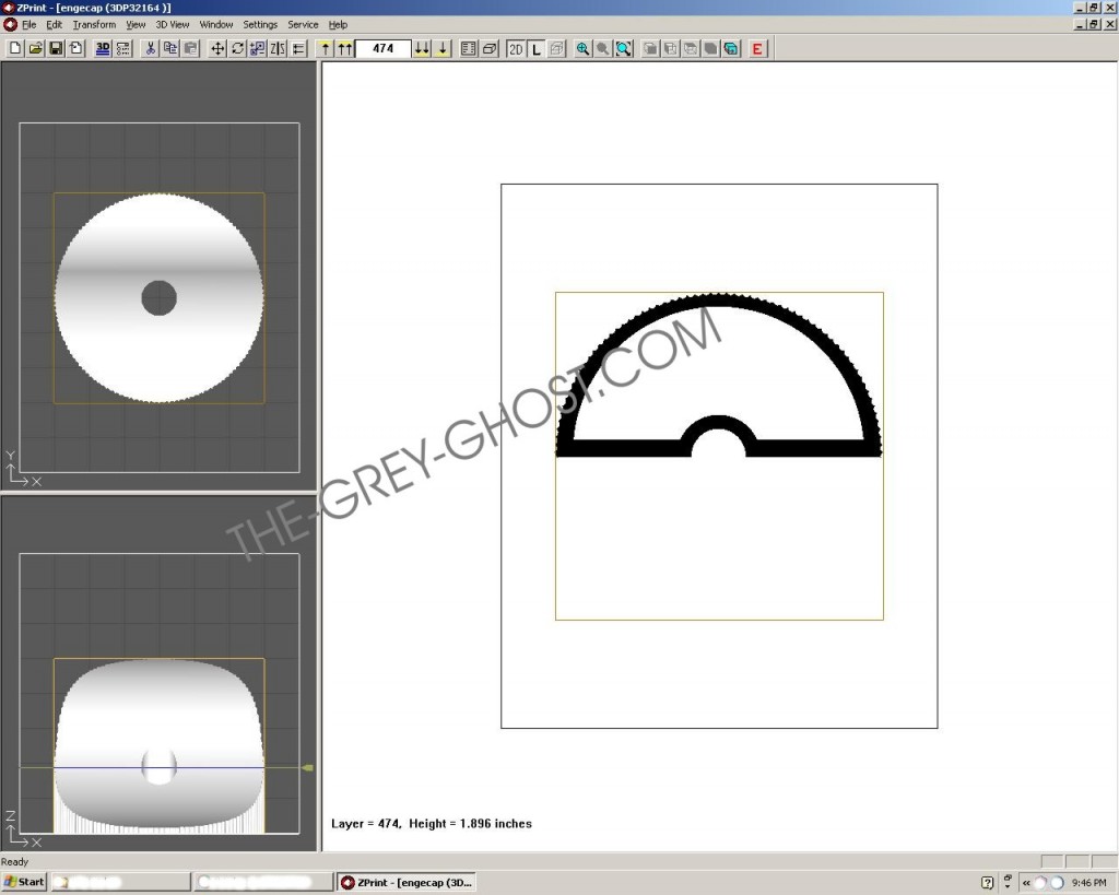
Here is why, this is the software that controls my 3d printer. It builds the part in layers, in this case each layer in .004″ thick. It’s very powerful and some of the simplest software I’ve ever used. But it comes at a price, you have a lot of work on the other end. The same thing thing goes for parts that come out of the router. No matter how fine I make the part, it still needs to be finished. That is why this stuff is done to make the next step easier.
More to come…

